Wiring harness design in CATIA V5 - 3D modeling Week 5 & 6 Challenge
Aim:
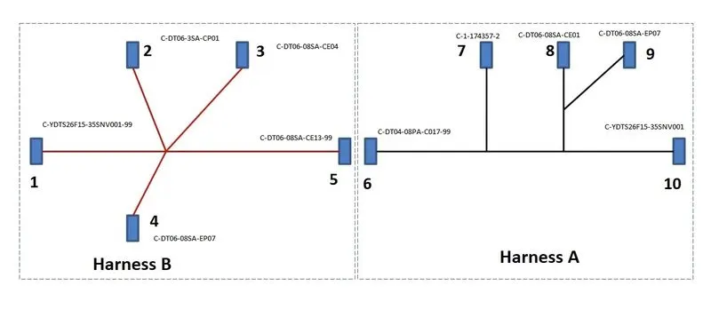
- To route the following harness layout.
- To check bundle continuity.
- Check for bundle warnings
- Generate CAT.part of the harness assembly and convert to .igs format
Theory: Connectors used are
- C-YDTS26F15-35SNV001-99
- C-DT06-3SA-CP01
- C-DT06-08SA-CE04
- C-DT06-08SA-EP07
- C-DT06-08SA-CE13-99
- C-DT04-08PA-C017-99
- C-1-174357-2
- C-DT06-08SA-CE01
Steps for Routing:
- Defining - All the connectors mentioned above are downloaded and defined geometrically and electrically. (Fig 1-8)
- Electrical Harness Assembly - Using the electrical harness assembly workbench, two seperate products are created, named harness A and harness B and the components are inserted and arranged according to the layout.(Fig 9 and Fig 10)
- Routing - Bundle segments are used to join connectors. Branch points are added and branches are defined assuming the diameter of each segment as 10mm and bend radius 1.4
Steps for Bundle Continuity check: Fig(11)(12)
- Go to Edit->Search->Advanced. Select the workbench as "Electrical", Type as "Bundle segment and Attribute as"Fully Connected".
- Select Query as "True".This will show all the connected bundle segments.
Steps for Connecting Harness A and B:Fig (13)
- A new product file named as "Wiring Assembly" is created under the electrical assembly design workbench. Harness A and harness B are copied to this file.
- Using "Connect" tool the male and female connectors(DT06-08SA CE13 and DT04-08PA C017) are connected electrically.
Steps for adding Annotations: Fig (14)
- A plane is selected for placing annotation using the command "View creation" in the electrical assembly design workbench.
- After selecting the front plane, annotation is placed using the command"Flag note with leader".
Lastly, the product file is converted to CATpart in the Mechanical assembly design using "Tools ->Generate9 CATpartfrom product". To save this file in .igs form select "File-> Save As", save as .igs file. Fig(15)
RESULTS: The results are as shown below.
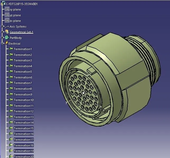
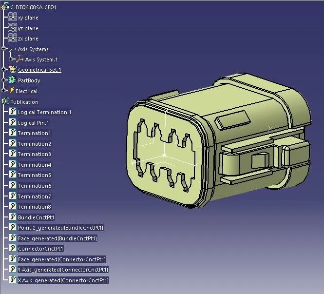
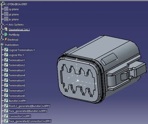
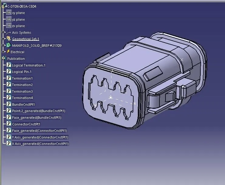
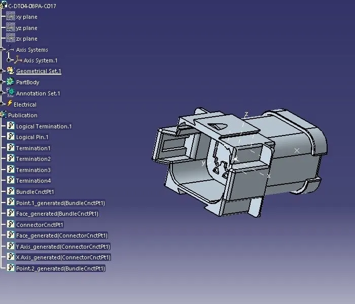
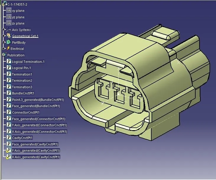
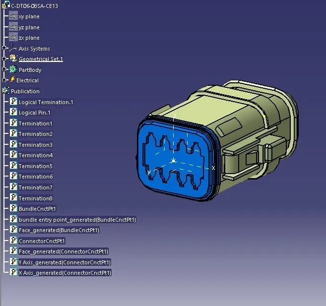
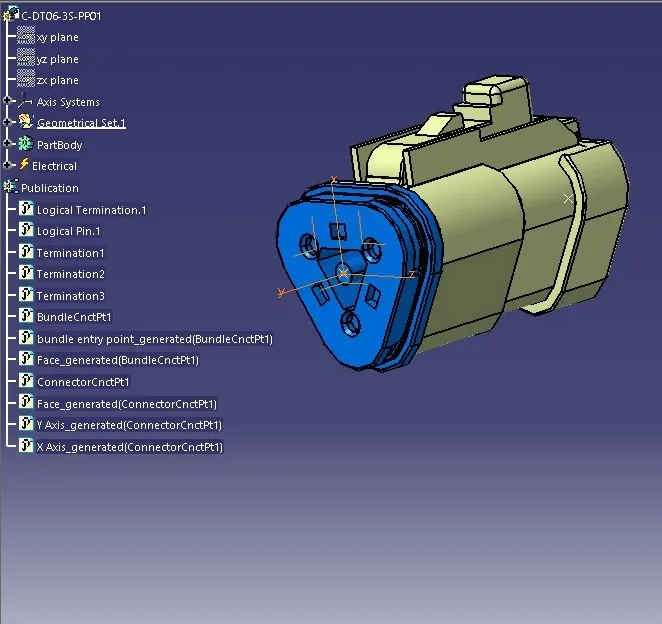
| FIG 1-8 (left to right) |
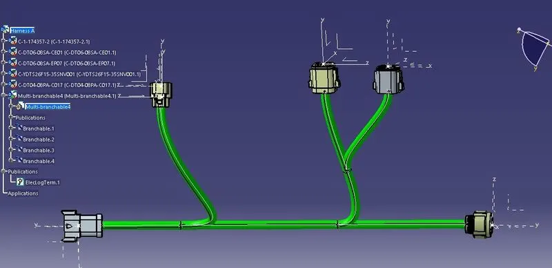
| FIG 9 Harness A |
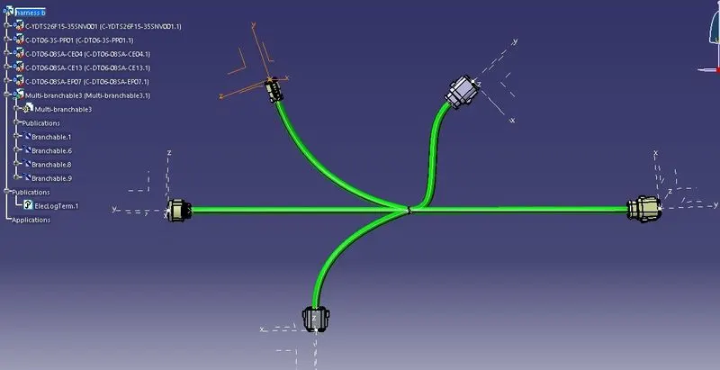
| FIG 10 Harness B |
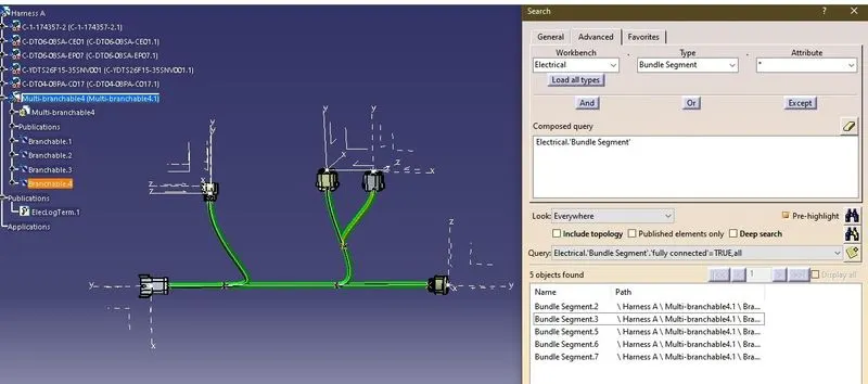
| FIG 11 Bundle continuity check of Harness A |
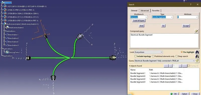
| FIG 12 Bundle continuity check of Harness B |
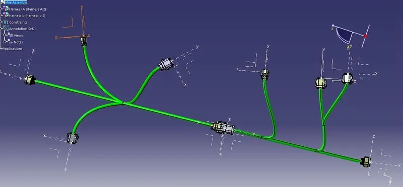
| FIG 13 Entire Asembly |
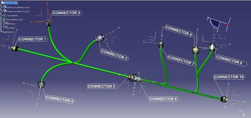
| FIG 14 Entire Wiring Assembly with Annotations |
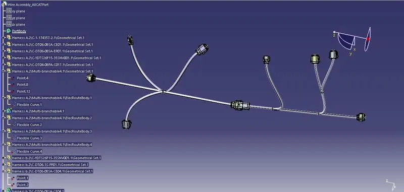
| FIG 15 CATpart of Entire Wiring Assembly |