Wiring harness design in CATIA V5 - 3D modeling Week 2 Challlenge
AIM: To define the connectors as electrical using Electrical part design workbench and to define all its properties.
Prerequisites: 3D CAD data of the connectors
Theory: The connectors defined here are Deutsch DT06 – 08SA and Tyco 174357-2. Deutch DT06 connector has 8 terminations. Tyco 174357 connector has 3 terminations and has locking facility . The mounting equipment used here is Tyco 85229-1.
Procedure:
- Create required geometrical parameters
- Define the bundle entry point.
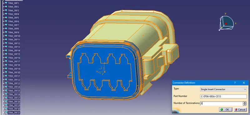
- Define part as connector
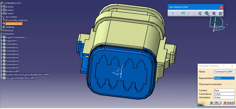
- Define bundle connection point
- Define connector connection point
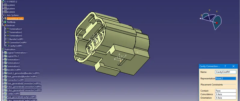
- Define cavity connection point (required only for Tyco 174357-2)
Results:
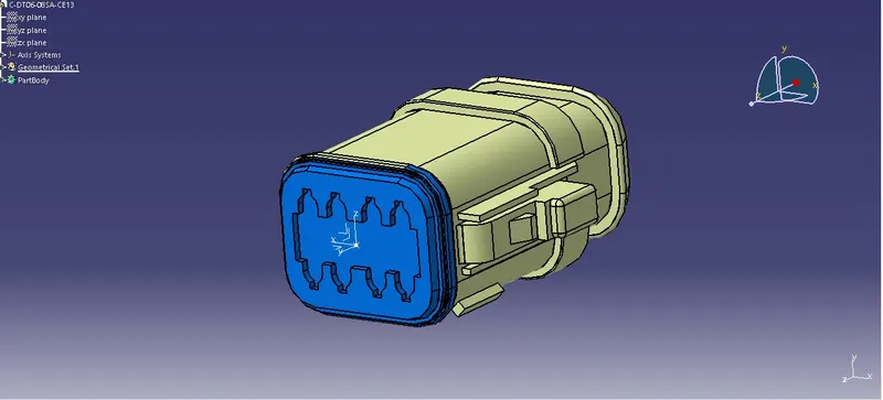
1. Deutsch DT06 – 08SA
- Geometrical parameters are defined
- The connector is defined as electrical
- Define bundle connection point and connector connection points.
2. Tyco 174357-2 with clip Tyco 85229-1
- After repeating the same procedure of defining bundle connection point and connector connection point, a cavity connection point is defined in TYCO 174357-2 as shown.
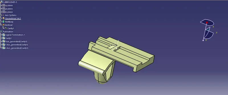
Now the connector clip properties are defined by defining the clip as mounting equipment and by defining cavity as shown
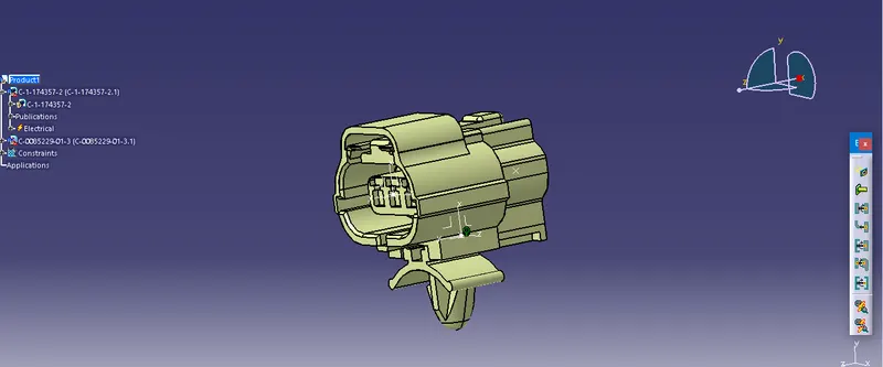
Both the clip and connector were imported as a new product using Electrical Assembly Design work bench. Here constraints are created between the mounting cavity and the connector.
Conclusion: Both the connectors Deutsch DT06 – 08SA and Tyco 174357-2 were defined electrically and all the necessary properties were defined.