Project 1
AIM: To route the wiring harness for the Bugatti V16 engine assembly and prepare the flatten view in CATIA V5.
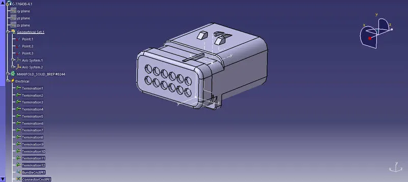
Theory: Bugatti V16 Engine has 16 fuel injejctor sensors and 4-cam shift sensors which will be connected electrically. Four pole connectors are used here for this purpose. The engine also icludes an interconnection connector to connect engine to other parts of the vehicle. A 12-pole connector with mounting clip feature is used as an interconnection connector.
Steps:
- Create the context assembly- This is the main assembly.The geometrical product file and additional sheet metal L-clip for placing the interconnection connector is added to this main assembly
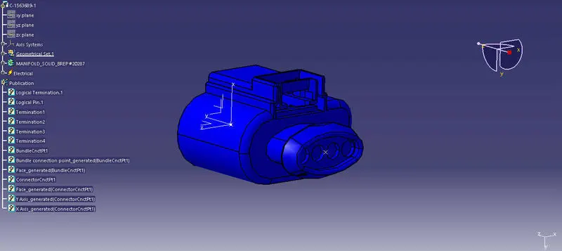
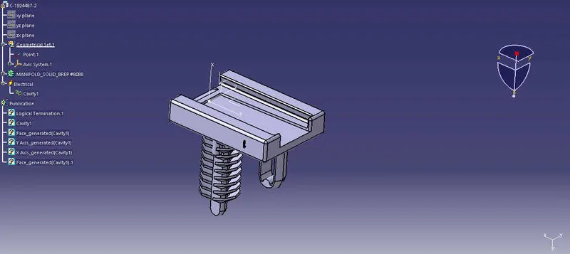
- Define the components- For this we first define geometrical parameters like points and axis.Then we define electrical parameters like connector connection point,bundle connection point and cavity connection point. Devices like guiding channels are defined as mounting devices and P-clamps are defined as supports .
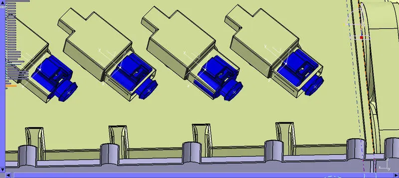
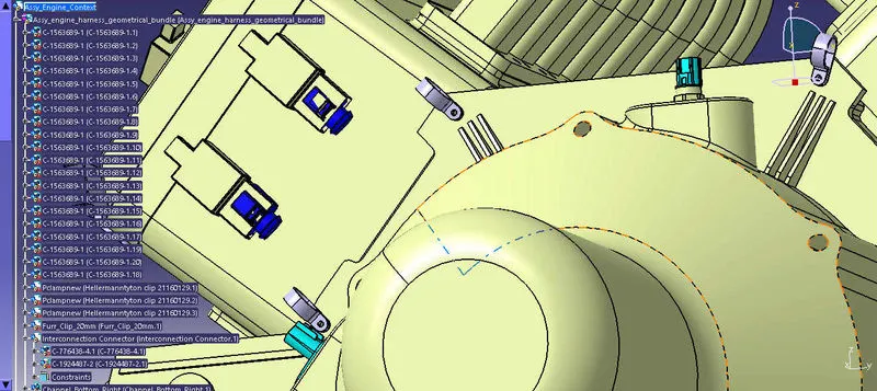
- Add the defined connectors to the geometrical Bundle product assembly and locating them on 16-fuel injector sensors slots and 4 -cam shift sensors slot.
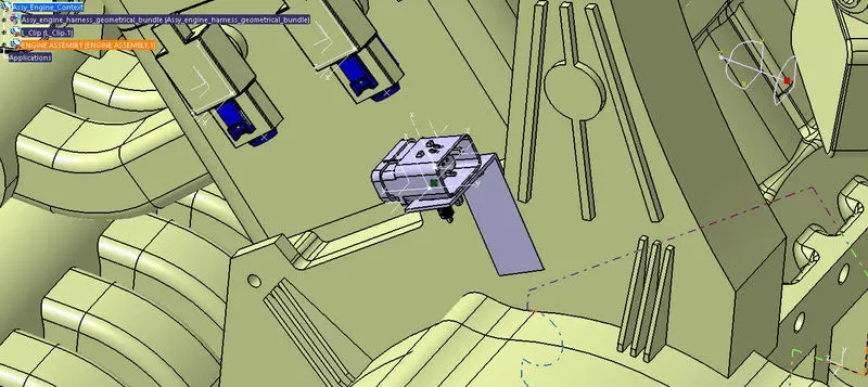
- Place the metal L-shaped bracket on the engine assembly. The bracket will be made to rest on the rib of the engine, such that it facilitates a locking mechanism and does not move freely.
- Define the interconnection connector with cavity clip and mount it on the L-bracket.
- Define and mount P-CLAMP on the engine
- Define and mount the guiding channels- Guiding channels protect the wiring harness from surrounding high temperatures, wear and tear, and provides nice aesthetics to the engine.
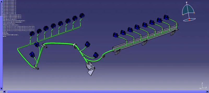
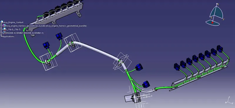
- Route all the components starting from interconnection connector and branches to cam-shaft sensors. The bend radius is assumed to be 1.4.The bundle diameter are assumed to be 15mm,10mm and 5mm. While routing some of these rules are kept in mind.
- Minimum distance between the clip to the branch point must be 25mm.
- Minimum distance between two branch points must be atleast 50mm.
- Branch length must be greater than 50mm.
- Proper tangency w.r.t the curve is applied.
- Addition of protective coverings to the harness.
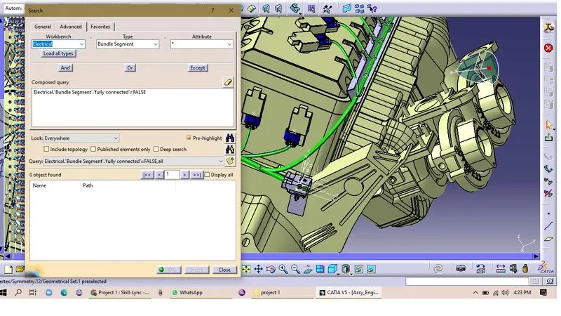
- Check for bundle continuity.
- Extract and flatten after setting the harness flattening parmaeters.
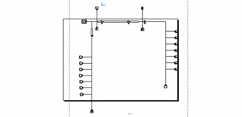
- Create the front view drawing of the flattened engine harness assembly.
Defined Components
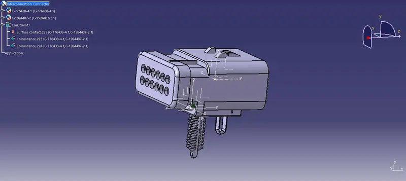
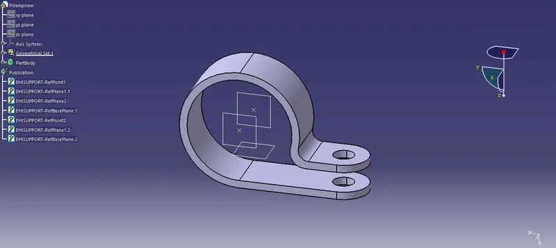
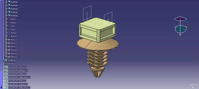
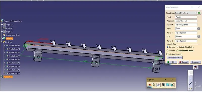
Placement of Components
Routing
Addition of COT Tubes
Bundle Continuity Check
Flattened Harness
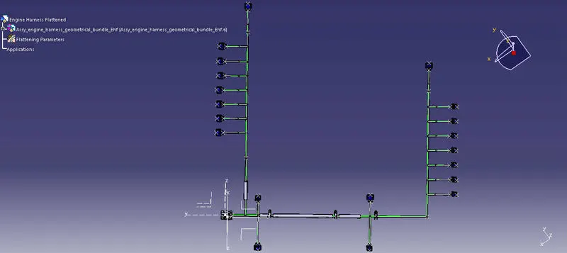
Front view of the Harness