Wiring harness design in CATIA V5 - 3D modeling Week 5 & 6 Challenge
Mayur Vispute
Project Report- Harness A & Harness B Assembly
Abstract - In this project we will create Harness A & Harness B and then assembly of Harness A & Harness B.
- Following steps we are followed :-
1) 1st of all electrical component like connector,clip,etc.,we have to define electrically.
2) Create a catalog for connectors and all connectors store in catalog.
3) Make product file for harness A and insert all connectors. Positioned them and create harness between them.
4) Apply protective covering on harness like, Cot tube, insulation tape as per requirement.
5) Finally give each and every connectors 3D Annotation.
6) step 3,4,5 same for Harness B.
7) Assembly of Harness A & Harness B.
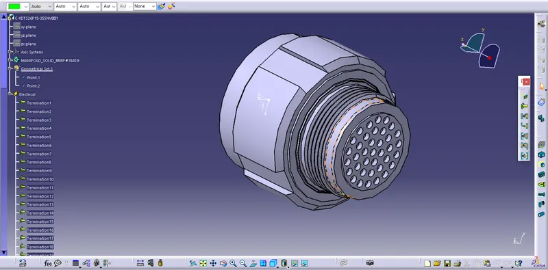
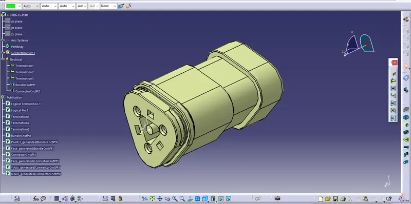
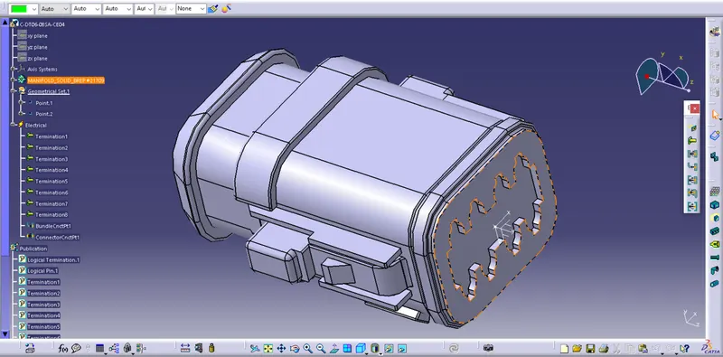
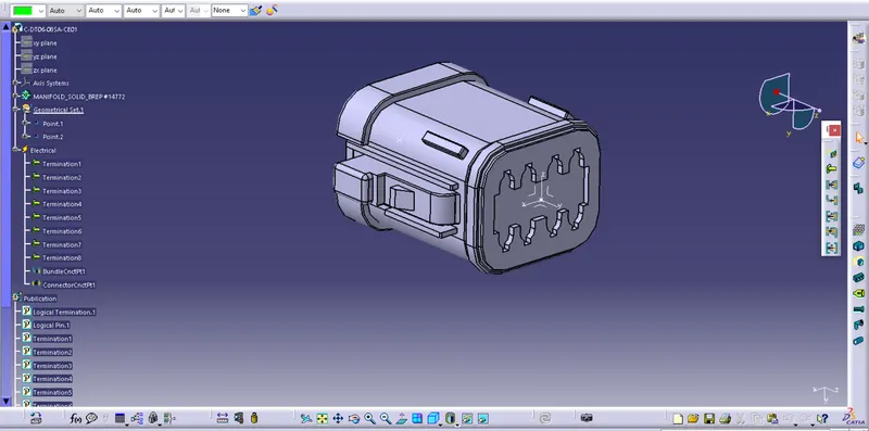
Step 1- Defined the Connectors Electrically & then used in this Project.
Connector-1 & Connector 10- c-ydts26f15-35snv001
Connector-2- c-dt06-3s-pp01
Connector-3- c-dt06-08sa-ce04
Connector-4 & Connector-8 - c-dt06-08sa-ce01
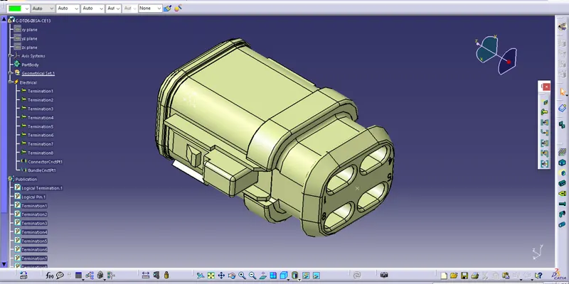
Connector-5- c-dt06-08sa-ce13
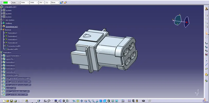
Connector-6- c-dt04-08pa-c017
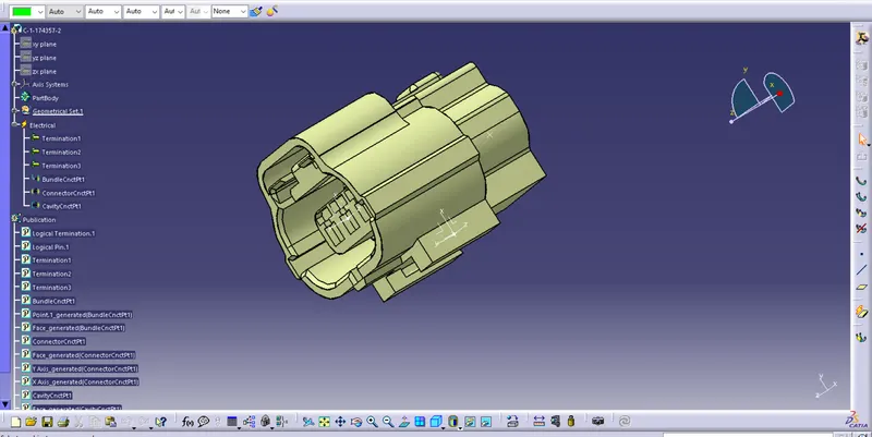
Connector-7- c-1-174357-2
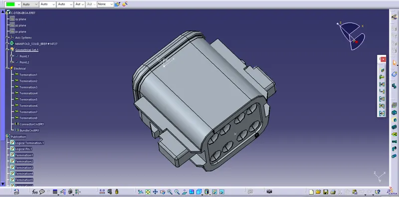
Connector-9- c-dt06-08sa-ep07
Step 2- Create Catalog for Connectors and Stored all connectors in this.
Step 3- Create Harness A and Harness B Seperately.
Steps For Harness Bundle Creation :-
- Create product file in CATIA.
- Add all required connectors from catalog and Switched into 'Electrically Harness Assembly' workbench , used command Geometrical Bundle for converting mechanical into electrical & then positioned them.
- Use command Multibranchable Document or Branch Defination to create bundle between connectors.
- To create sub branch use command Add Branch Point.
- To apply cot tube or insulation tape over bundle use command Protective Covering.
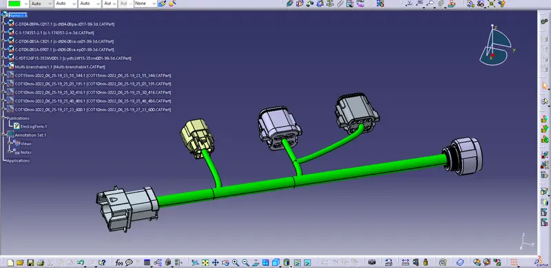
Harness A- Without COT Tubes.
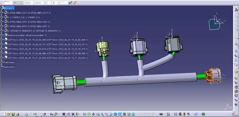
Harness A- With COT Tubes.
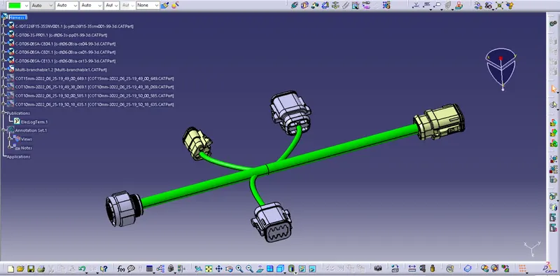
Harness B- Without COT Tubes.
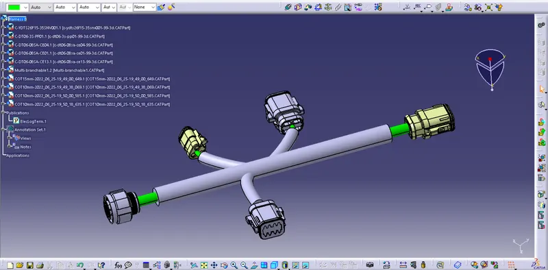
Harness B- With COT Tubes.
Step 4- Check Warnings and Clear this warnings by using Following options-
- Shift branch point location.
- Change bend radius or apply slack.
- Provide Tangency.
Here we are able to see some warning show in branch no. 4
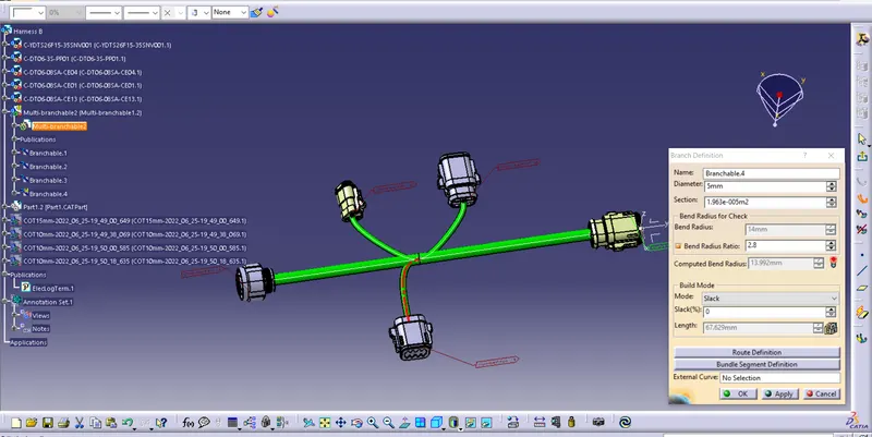
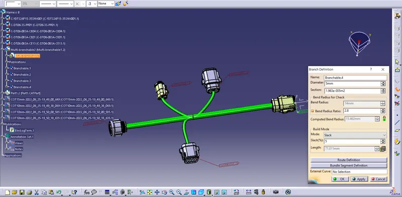
To remove this warning , I give 5% Slack for that branch and warning get cleared. Due to slack bend radius changed and its greater than desired.
Step 5- Assembly of Harness A and Harness B.
Interconnection of Harness A & Harness B-
Steps for Interconnection :-
- Create a new product file.
- Our already created product file of harness A and Harness B copy and paste in new product file.
- Used Compass, Manupulation, Snap and Smart Move commands to interconnects Harness A and Harness B.
Assembly of Harness A & Harness B with 3D Annotation-
Steps for 3D Annotation :-
- Switch into Assembly Design workbench.
- Make sure geometrical bundle is active.
- Select View Creation/annotation plane icon and create plane where we use for annotation.
- Select Flag note with ladder icon and then select reference point on part you wish to add the annotation to.
Step 6- Check Bundle Connectivity-
From this snap we able to see , each and every bundles are connected.
THANK YOU