Wiring harness design in CATIA V5 - 3D modeling Week 4 Challenge
Mayur Vispute
Wiring Harness Design
Step 1- In this wiring harness design we use four different types of connector.
- first of all, all connector we have to define electrically.
-Step to Define Connectors-
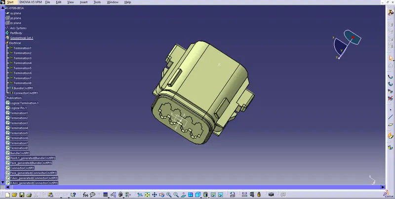
- In Part design , define geometrical parameters like entry point, exit point, axis.
- Switch into Electrical part design, define electrical parameters like define as connector, define bundle connection point, define connector connection point.
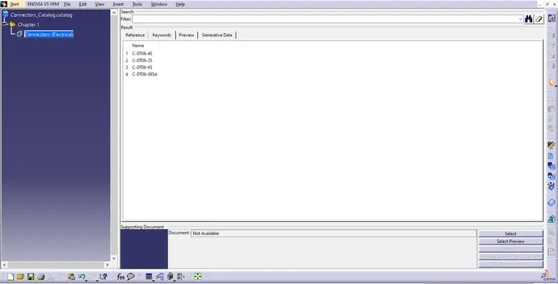
Electrically Defined Four Connectors given below-
DT06-2s
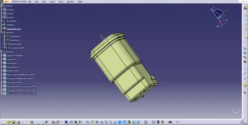
DT06-4s
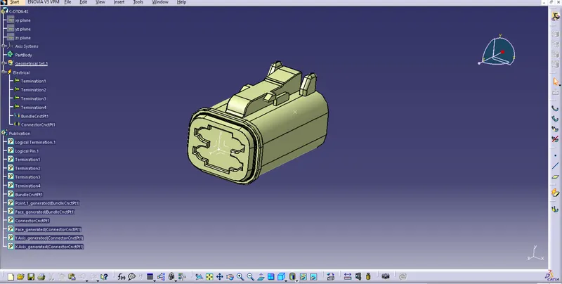
DT06-6s
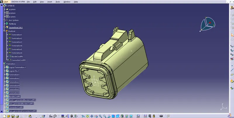
DT06-8sa
- All 4 connectors store in catalogue.
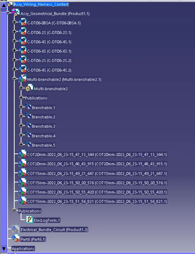
Step 2- Create main product file ( Assy wiring Harness Context ) and sub product file ( Assy Geometrical Bundle ).
Step 3- Add our four connectors by using calalogue browser command.
- Switch into Electrical Harness Assembly.
- Use 1st Command Geometrical Bundle to convert Mechanical into Electical.
Step 4- Possitioning all the connectors with help of sketch.
-Steps for Sketch:- Go to Start-Mechanical Design-Sketcher.
- After Completing the sketch , copy the sketch and paste in our main product file.
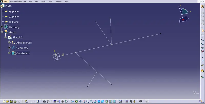
Step 5- Switch into Electrical Harness Assembly.
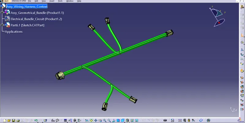
- Use Command Multibranchable Document for creating wire between connectors.
- Then use command Add Branch Point for sub branches.
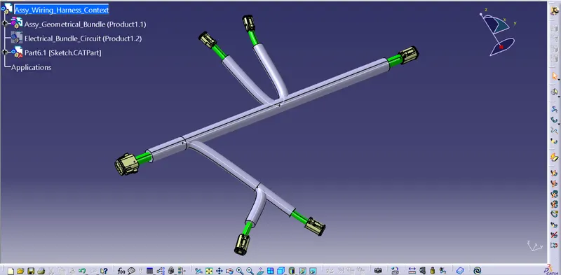
- and last use command Protective Covering for covering wires by COT tubes and Insulation tape.
Multibranchable-
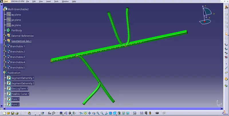
Harness Routing without Cot Tubes-
Harness Routing with Cot Tubes-
Command History-