Wiring harness design in CATIA V5 - 3D modeling Week 2 Challlenge
Mayur Vispute
PROJECT REPORT
ABSTRACT - Convert the CAD data of electrical equipnment into electrical properties. 1st of all , I download the cad data of component then using CATIA V5 I define geometrical parameters in part design workbench. After that i switch into Electrical part design workbench to define all electrical properties to component.
1) CONNECTOR :- A) Deutsch DT06-08SA
B) Tyco 174357-2 (with Cavity)
A) Connector Deutsch DT06-08SA :-
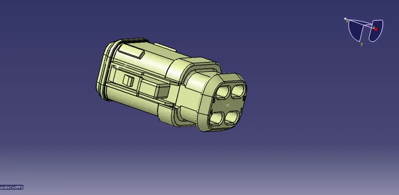
Feature Tree :-
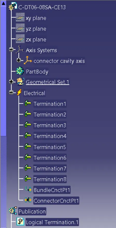
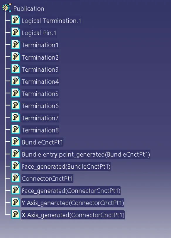
Steps :-
- In Part Design Workbench , 1st I defined the some geometrical properties like Point & Axis to cad file of connector.
- Switch into Electrical Part Design Workbench.
- Used command "Define Connector" to define 'Single Insert' & '8 Port Connection'.
- Used command "Define Bundle Connection Point", In which select representation as a normal face of a bundle direction , then select a point & for initial condition again select a normal face.
- Used command "Define Connector Connection Point" , In which select Representation as a point or face, Cotact as point, Coincidence is Y-axis, and Orientation is X-axis.
- & last store the connector in connector cataog by using command "Store Device".
B) Tyco 174357-2 (with Cavity) :-
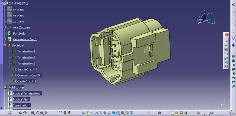
Feature Tree :-
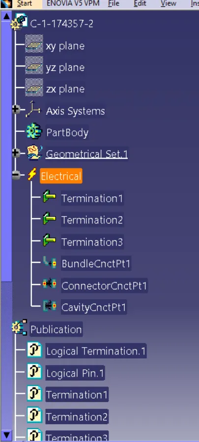
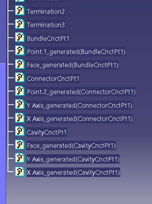
Steps :-
- In Part Design Workbench , 1st I defined the some geometrical properties like Point & Axis to cad file of connector.
- Switch into Electrical Part Design Workbench.
- Used command "Define Connector" to define 'Single Insert' & '3 Port Connection'.
- Used command "Define Bundle Connection Point", In which select representation as a normal face of a bundle direction , then select a point & for initial condition again select a normal face.
- Used command "Define Connector Connection Point" , In which select Representation as a point or face, Cotact as point, Coincidence is Y-axis, and Orientation is X-axis.
- Used command "Define Cavity Connection Point" , In which select Representation as a point , Cotact as locking face, Coincidence is Y-axis, and Orientation is X-axis.
- & last store the connector in connector cataog by using command "Store Device".
2) MOUNTING CLIP :- Tyco 85229-1
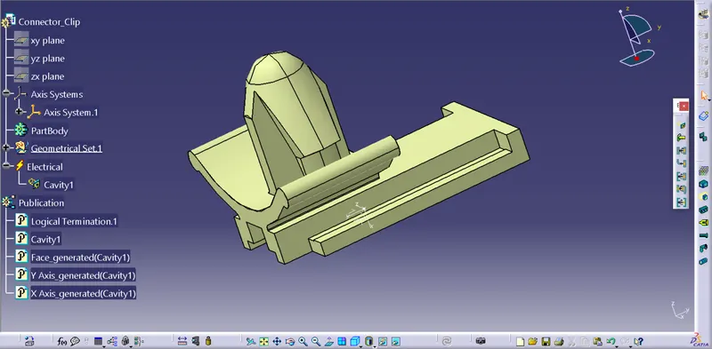
Feature Tree :-
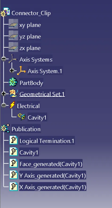
Steps :-
- In Part Design Workbench , 1st I defined the some geometrical properties like Point on mating area & Axis to cad file of connector clip (x direction towards locking side, y direction towards insertion & z direction towards right or left). & Save it.
- Switch into Electrical Part Design Workbench.
- Used command "Define Mounting Equipment" to 'Connector Clip'.
- Used command "Define Cavity", In which select representation as a Point, Contact as a Mating face, Coincidence is Y-axis, and Orientation is X-axis.
- & last store the connector in connector cataog by using command "Store Device".
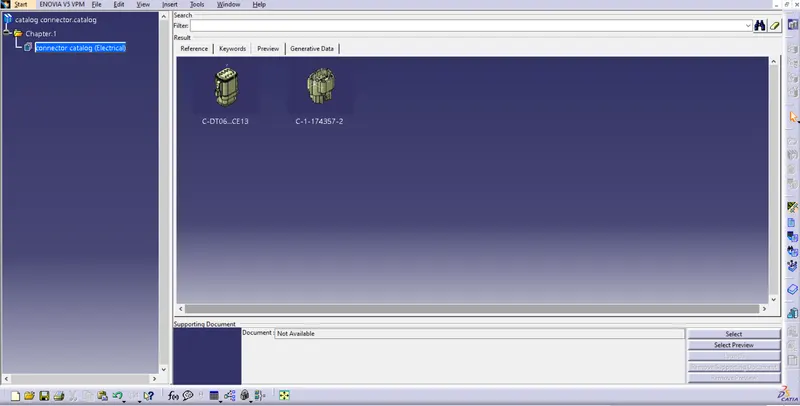
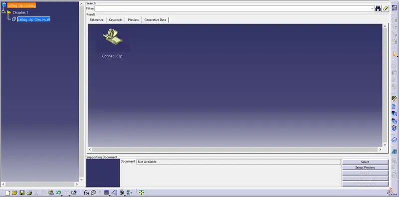
CATALOG CREATION :-
- Go to FILE select NEW then select CATALOG DOCUMENT and OK.
- Use command "NEW FAMILY" & put name whatever we want for eg., CATALOG CLIP or CATALOG CONNECTOR and then select type for eg., STANDARD or ELECTRICAL, etc..
- Go to file and save it in catalog folder.
- Now if we have to store part in catalog then, Use command "STORE DEVICE" and in popup window, select catalog location and family.
Connector Catalog Preview :-
Clip Catalog Preview :-
THE END