Radar Mast & Final Assembly of Yacht
Mayur Vispute
1. Radar Mast
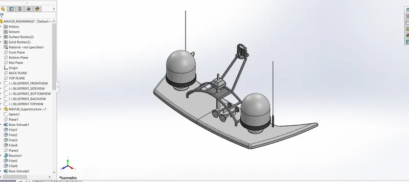
Isometric View-
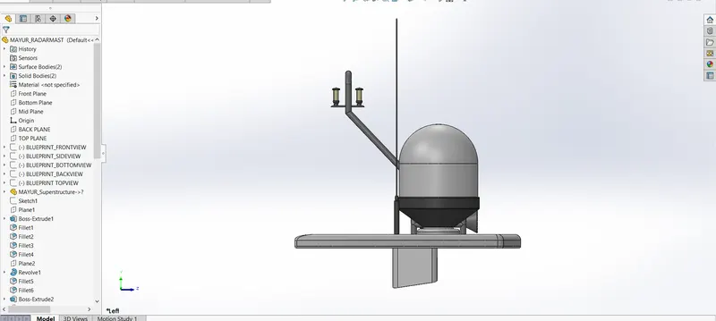
Side View-
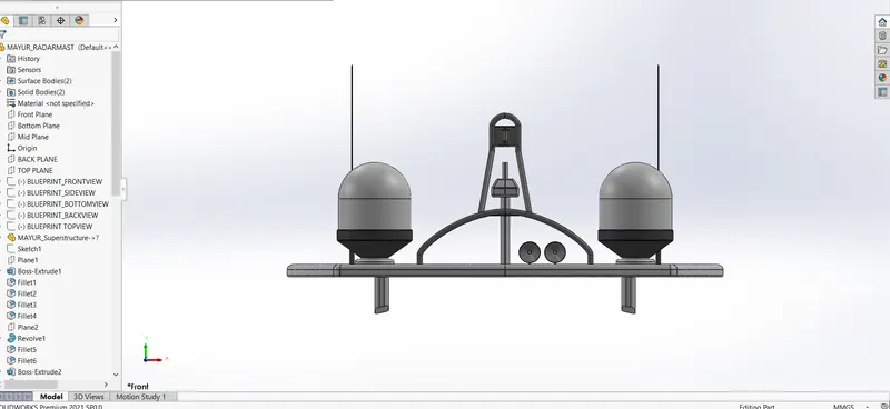
Front View-
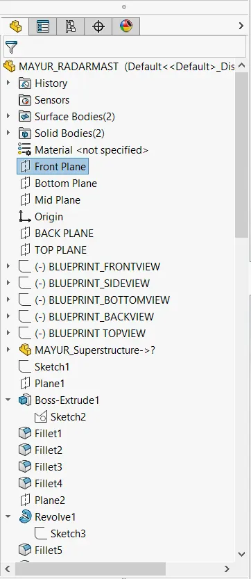
Command History-
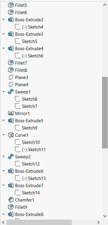
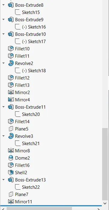
2. Yacht Assembly-
Isometric View-
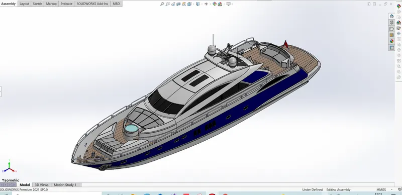
Side View-
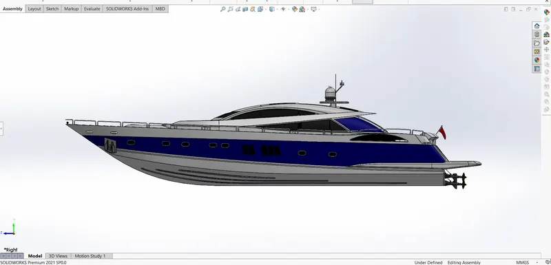
Front View-
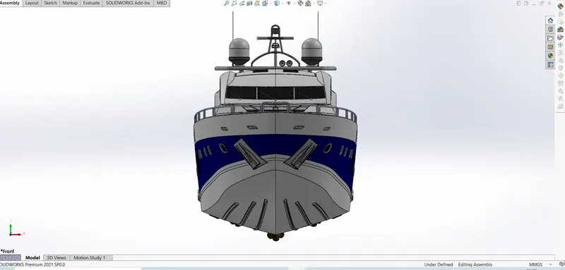
Command History-
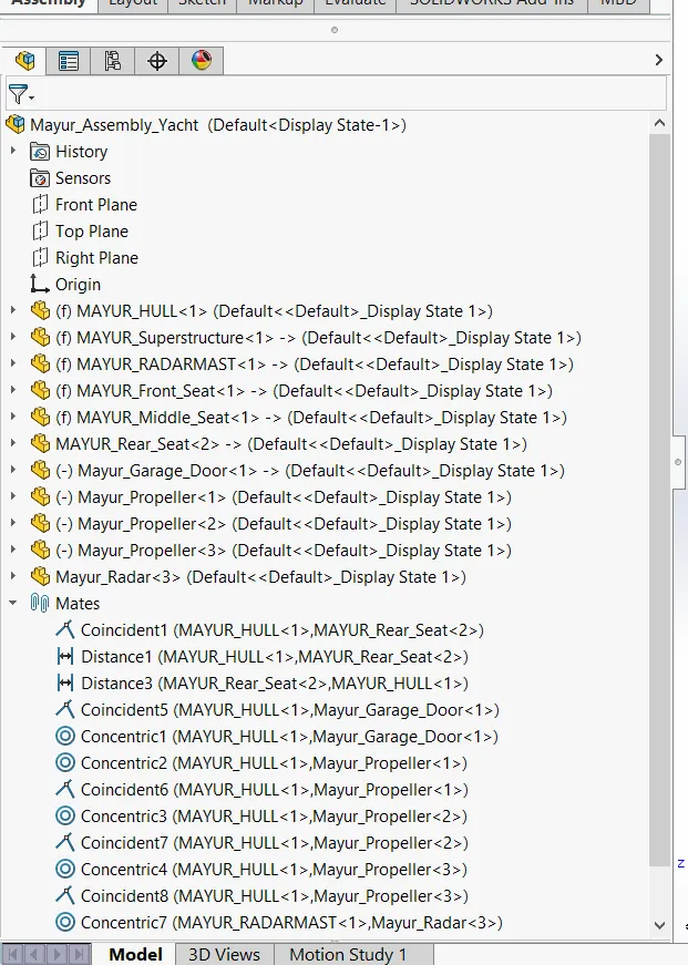

Project Report-
MODELLING OF PREDETOR YACHT ON SOLIDWORKS.
INTRODUCTION
In this project I learn about the design of Predetor Yacht assembly with help of SOLIDWORKS. By using blueprint sketch, I get idea of sketching the parts and its dimensions. After designing all the parts I do assembly of Yacht. After assembly I add decals, lights, camera and do rendering of Yacht by using SOLIDWORK & PHOTOVIEW 360.
The components which I learnt in Yacht are:-
- Propeller
- Radar
- Hull
- Garage Door
- Front Seat
- Middle Seat
- Rear Seat
- Superstructure
- Radar Mast
OBJECTIVE
- To learn the basic commands of SOLIDWORK.
- With the help of blueprint sketch we design all the parts of Yacht.
- While designing the yacht, I had to do a lot of Surface commands successfully, So because of this I understood the surface commands very well.
- Assembling all the parts in SOLIDWORK.
- Get the knowledge of concepts like decals, light and camera angle.
- Proper setting of image quality and getting realistic view with the help of photoview 360 & also Rendering of Predetor Yacht has done with help of photoview 360.
DESIGN APPROACH
There are two types of approach in design procedure.
- Bottom up approach
- Top down approach.
Here in this project we have used Bottom-up approach, we get clear idea by defining these terms.
- Bottom up approach: The design approach in which the most primary operations are specified first then combined it later to make larger progressive unit.
- Top down approach: Top down assembly modelling is an assembly-centric modelling method where the assembly design is started at the highest level possible, and individual parts and subassemblies are defined within the context of the overall assembly.
FLOWCHART
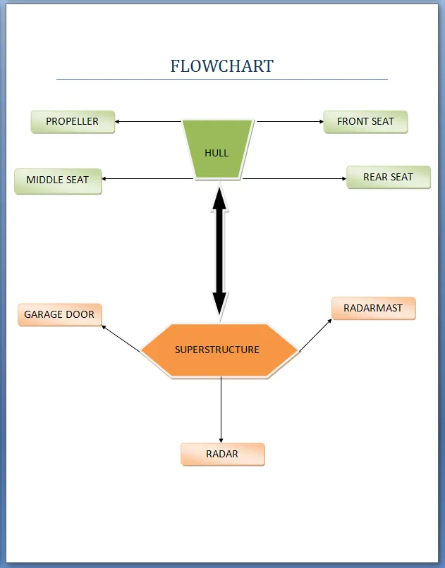
I used the following features and properties in the entire model to design different parts:-
- Surface Extrude
- Surface Loft
- Surface Fill
- Surface Knit
- Surface Trim
- Surface Sweep
- Ruled Surface
- Dome
- Swept Boss/Base
- Revolved Boss/Base
- Extrude Cut
- Mirror
- Linear Pattern
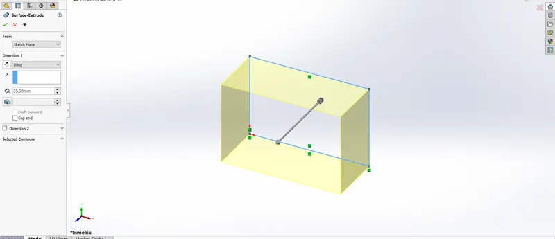
Surface Extrude:-
Using the surface extrude feature, we can extrude the boundary edges of a face of a solid body or edges of a surface body in a customized direction.
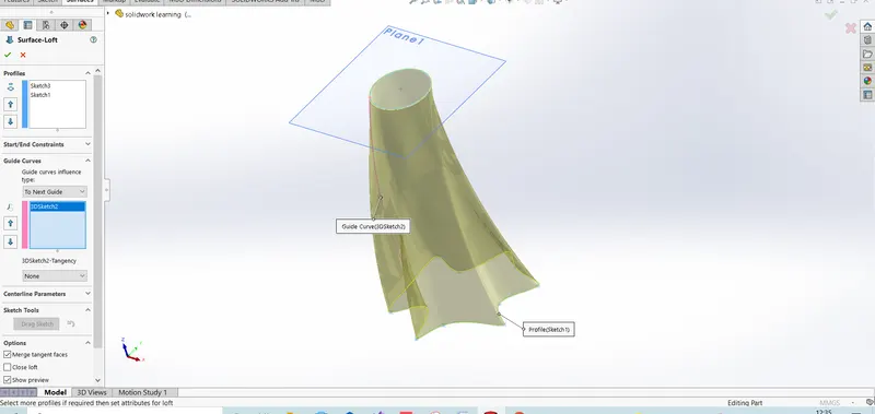
Surface Loft:-
The loft feature is an important tool for (surface) modeling in SolidWorks. The loft feature creates a shape by making transitions between multiple profiles and guide curves. This tool is very valuable for modeling complex surfaces. We can do some really cool stuff when we use this feature properly.
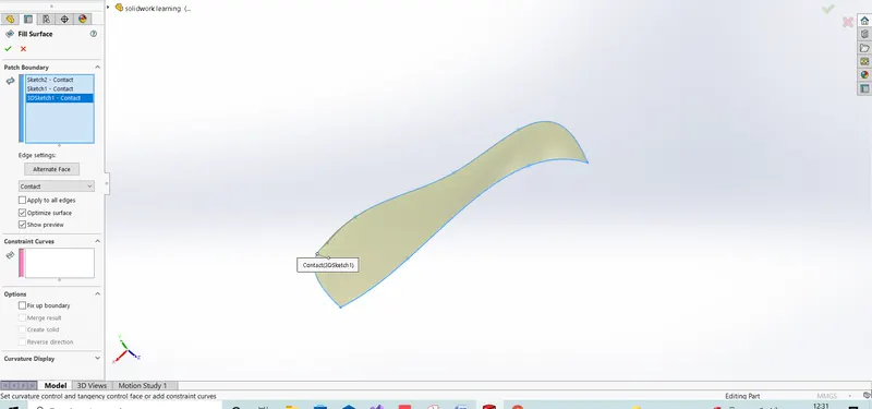
Surface Fill:-
The Filled Surface feature constructs a surface patch with any number of sides, within a boundary defined by existing model edges, sketches, or curves, including composite curves. We can use this feature to construct a surface to fill a gap in a model.
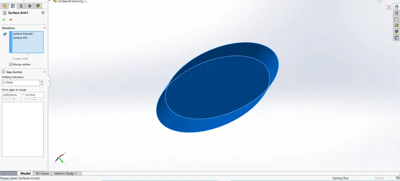
Surface Knit:-
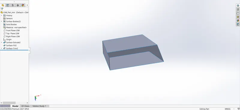
Use the Knit Surface tool to combine two or more faces and surfaces into one. Note the following about knit surfaces: Edges of the surfaces must be adjacent and not overlapping. Surfaces do not need to be on the same plane.
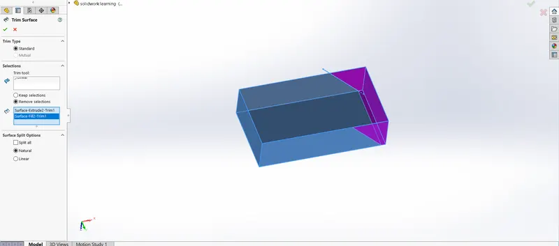
Surface Trim:-
We can also use a surface in conjunction with additional surfaces, as mutual trim tools. Trim surface includes the following options: To trim a surface: Create two or more surfaces that intersect at one or more points, or create a surface that intersects with a plane or has a sketch on its face.
Surface Sweep:-
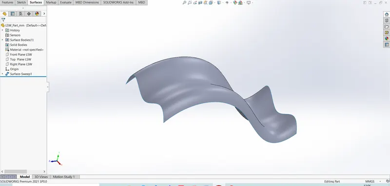
To create a swept surface, Create planes for sketching the sweep profile, sweep path, and if necessary, the guide curves. Sketch the sweep profile and path on the planes that we created. We can also sketch the sweep path on a model face or use a model edge for the path.
Ruled Surface:-
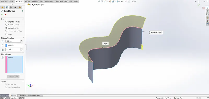
Ruled surface is tangent to the surfaces that share an edge. Normal to Surface. Ruled surface is normal to the surfaces that share an edge. Tapered to Vector. Ruled surface is tapered to the specified vector.
Dome:-
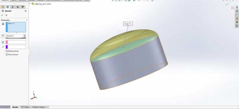
For Dome feature we have select face. In Dome feature two types of dome is there, one of is circular and another one is elliptical. Example: Applying a Dome to Irregular, Non-Planar Faces. A dome is a hollow half of a sphere. Domes are one of the most familiar features in architecture, frequently used for government and religious buildings.
Swept Boss/Base:-
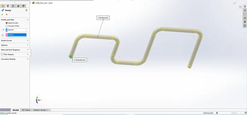
Solidworks Swept boss is one of the useful features which help to sweeps a closed profile through an open or closed path. For this command required two sketch on two different plane. In first sketch consist of profile sketch and in second sketch consist guide curve.
Revolve Boss/Base:-
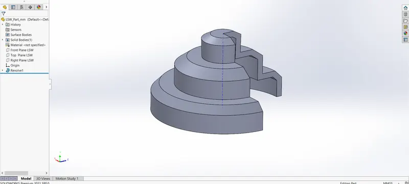
This feature works around an axis, by selecting axis of a sketch it adds a round material by revolving around that axis. If there is no axis we can select an edge of a sketch and it gives us appropriate geometry.
Extrude cut:-
It cuts the geometry which we don’t need from the part or it can be used to give the desired shape to the sketch or solid part. When we draw sketch on the solid part and then we use extrude cut command it removes that part/surface.

Mirror:-
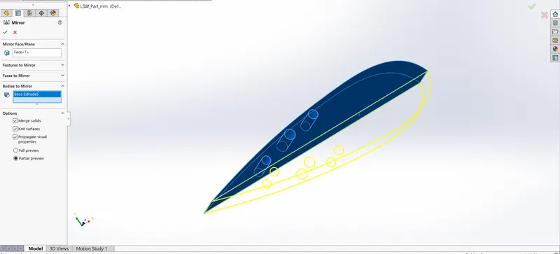
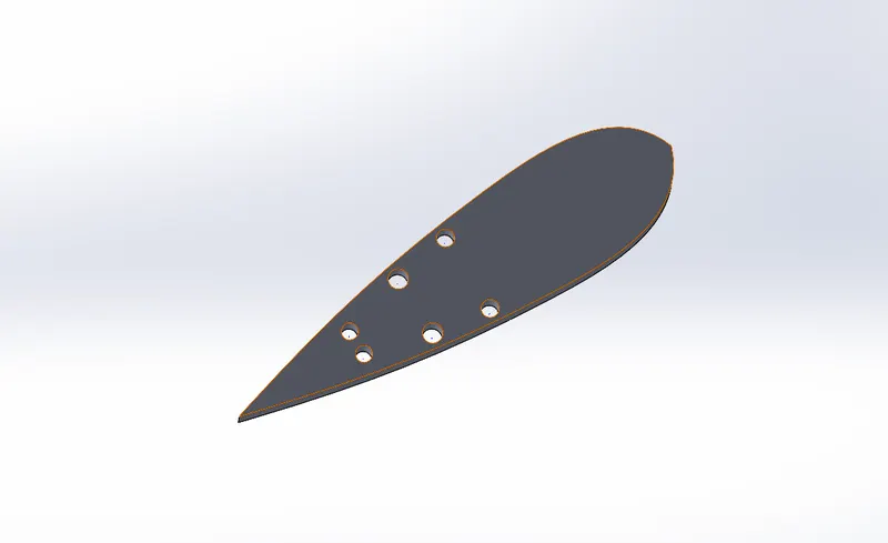
This feature creates copy of solid part. When this feature is applied it need plane or axis to mirror. Select the body which is to be mirror, select an axis or plane then apply feature and the mirrored part will get.
Linear Pattern:-
Use linear patterns to create multiple instances of one or more features that you can space uniformly along one or two linear paths. Create one or more features to replicate.
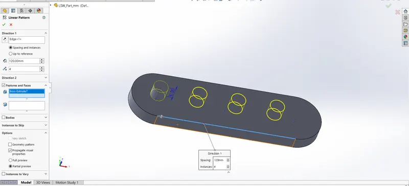
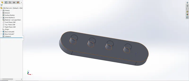
Following are the parts of the Predetor Yacht. Let us discuss part by part of Yacht.
Propeller:-
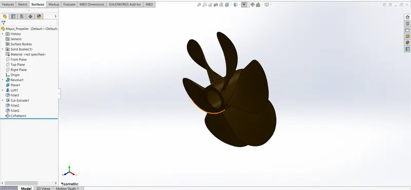
A propeller is a device with a rotating hub and radiating blades that are set at a pitch to form a helical spiral, that, when rotated, exerts linear thrust upon a working fluid, such as water. Propellers are located at rear side of yacht. The commonly used material for this is Alloy of aluminum and stainless steel. It is a solid body.
Features used to create the propeller:-
- Sketch
- Revolve
- Extrude Cut
- Fillet
- Circular Pattern
- Appearance
Radar:-
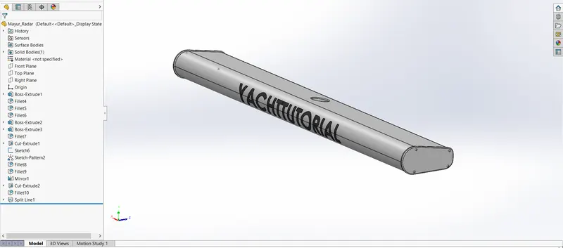
While designing the radar, first I used sketch command after completing the sketch then extruded. Use extrude cut command for fixing the radar on radar-mast. Creating a sketch of allen bolt then used Sketch pattern command. “YACHTTUTORIAL” name created with the help of split line command.
Features used to create the Radar:-
- Sketch
- Extrude
- Fillet
- Cut Extrude
- Sketch Pattern
- Mirror
- Split Line
Hull:-
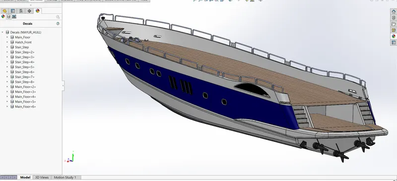
Here I use maximum surface commands to create a hull because hull having complex and variable shape so we can easily achieved by using surface commands. Projected curve command use to create hull shape. Surface loft and surface fill use for outer body of hull, and very important surface knit command converted two or more faces into single surface. Extra surface deleted by using surface trim option. Surface offset use to create a deck surface, And deck surface very important to creating a sketch of front seat, middle seat, rear seat on that, Due to this assembly very easily done.
Features used to create the Hull:-
- Sketch
- Projected Curve
- Surface Extrude
- Surface Loft
- Surface Trim
- Knit Surface
- Surface fill
- Sweep
- Helix Spiral
- Linear Pattern
- Delete Face
- Offset Surface
Garage door:-
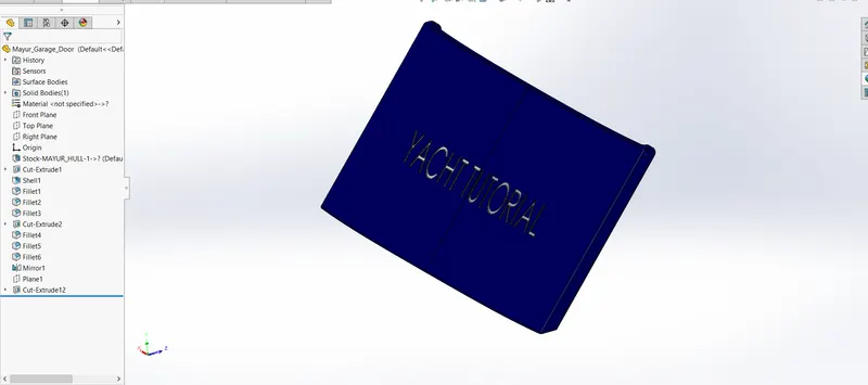
For the Garage door I used the removal stock of garage space. By using the stock, I used sketch command on that stock material. After completing the half door, mirror command used to complete full door. Appearance and Text use on garage door.
Features used to create the Garage Door:-
- Sketch
- Shell
- Fillet
- Extrude Cut
- Mirror
Front Seat/Middle Seat/Rear Seat:-
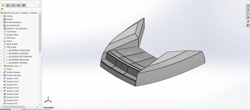
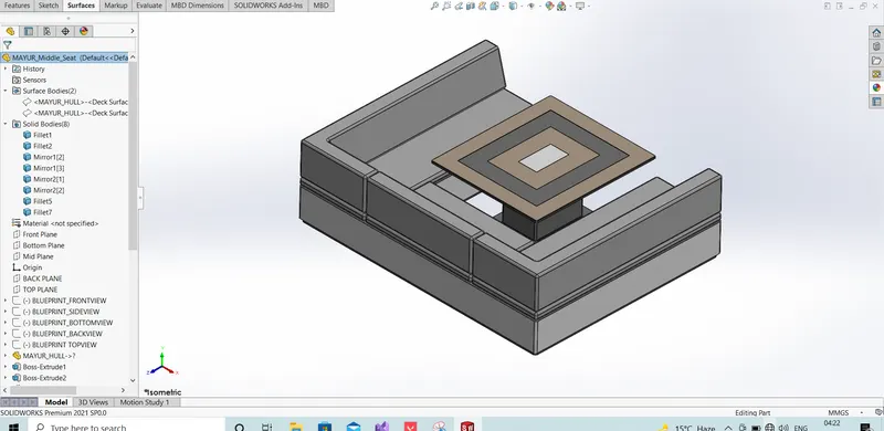
The material of the seats adopt fire-proof leather, PU/PVC leather or fabric according to customer requirements. The anti-corrosion aluminum structure is durable. They all have beautiful appearance and special design which makes people more comfortable when seating.
Features used to create the Seats:-
- Surface Sweep
- Surface Extrude
- Surface Trim
- Surface Loft
- Surface Knit
- Surface Fill
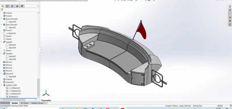
Front Seat-
Middle Seat-
Rear Seat-
Superstructure:-
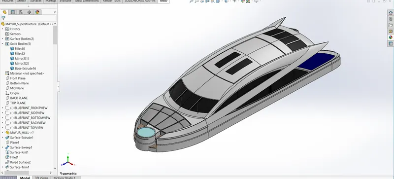
To create Superstructure, I use the deck surface of hull. The size of superstructure has a great influence on the mobility of the vessels. They are designed in a manner, so that, they add value and hinder the speed and mobility in the least. The superstructure is mostly designed in fashion as well. First I use surface command to create superstructure, after completing the one side of structure then convert into solid form and mirror it.
Features used to create the Superstructure:-
- Ruled Surface
- 3D Sketch
- Fillet
- Mirror
- Surface Sweep
- Surface Extrude
- Surface Trim
- Surface Loft
- Surface Knit
- Surface Fill
Radar mast:-
A Radar (Radio Detection & Ranging) is an instrument that can detect surrounding objects using radio waves. Thus, in the maritime world, objects such as ships, buoys or birds can be detected by radars.
Features used to create the Radar mast:-
- Sketch
- sweep
- Circles
- Fillet
- Revolve
- Dome
- Chamfer
- Mirror
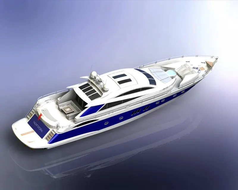
Assembly of the Predetor Yacht:-
All the parts were modelled and were imported to assemble them. In assembly mate feature is most commonly used to locate and relate the parts with one another. Hull is main component which is inserted first and then fixed. The other components were inserted one by one and with the help of deck surface they all are automatically getting their position.
Decals:-
A decal is something called a “transfer”, and it consists of a picture, image, pattern, or design that’s printed on metal body. We have added decals on Hull floor, Stairs, Garage area of yacht. It gives nice appearance to the Yacht.
Rendering:-
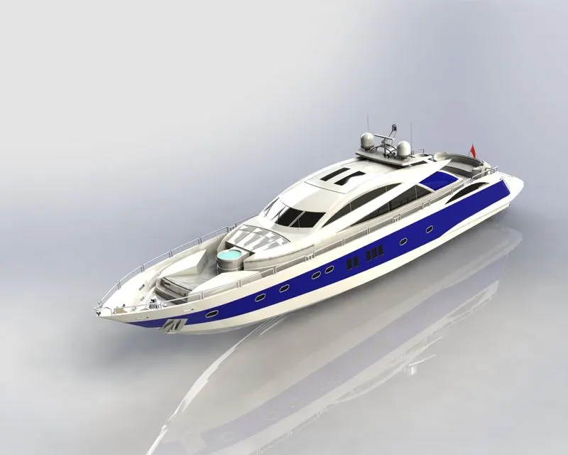
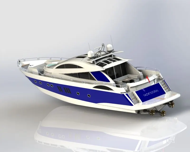
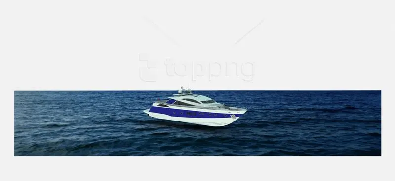
The term rendering comes from the graphic world where a rendering is an artistic drawing of what a new structure would look like. In Computer Aided Design (CAD), a rendering is a particular view of a realistic image. By doing rendering of Yacht we get the idea that how it will look into the environment. This rendering is done in the PHOTOVIEW 360. By using PHOTOVIEW 360 we can add various camera views to the model, we can set various angles, direction, and can set appropriate distance to get the perfect camera view. In rendering we change color of Yacht parts, background images, brightness, rotation and various setting of Yacht. Including the resolution and setting number of passes we get more detail visual’s of Yacht.
THANK YOU