Wiring harness design in CATIA V5 - 3D modeling Week 5 & 6 Challenge
Aim: To Route the following harness layout in the Electrical workbench and make assumptions for harness bundle diameters by using the connectors provided.
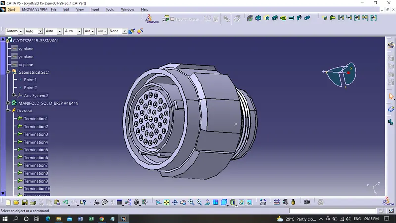
converting the Connectors of Harness A and B from mechanical to electrical parts and defining it as a connector:
Harness_A connectors:
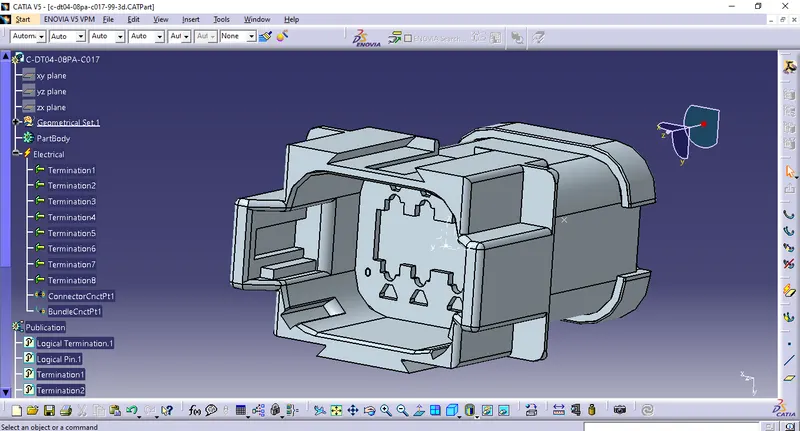
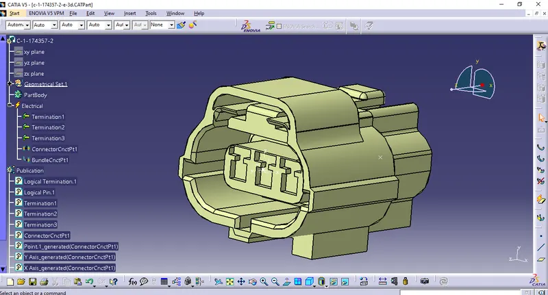
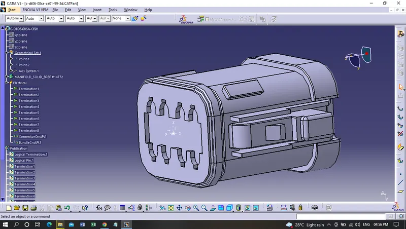
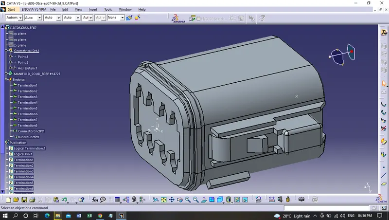
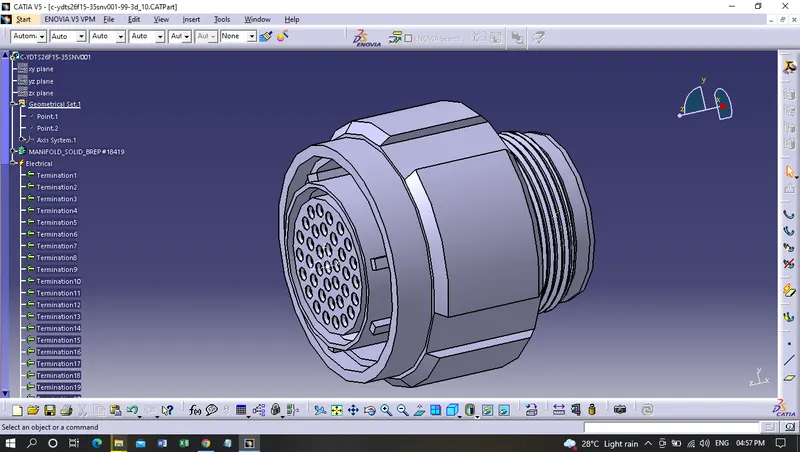
Harness_B connectors:
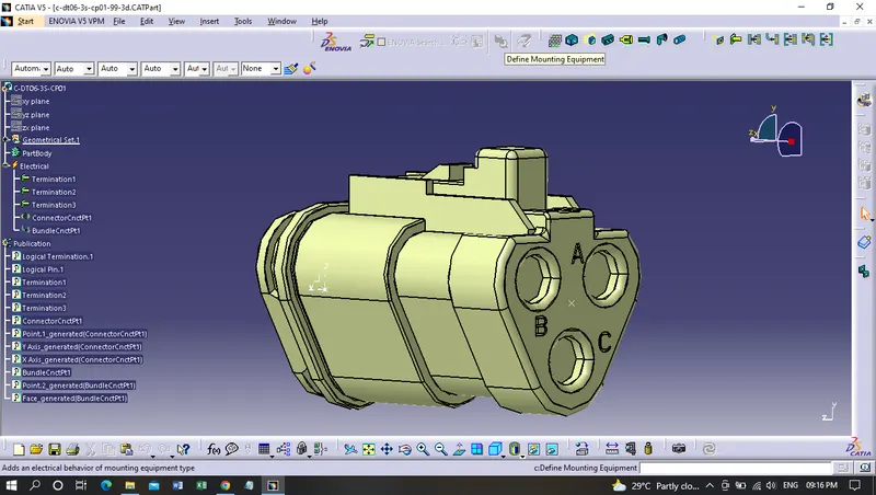
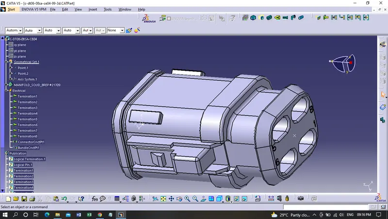
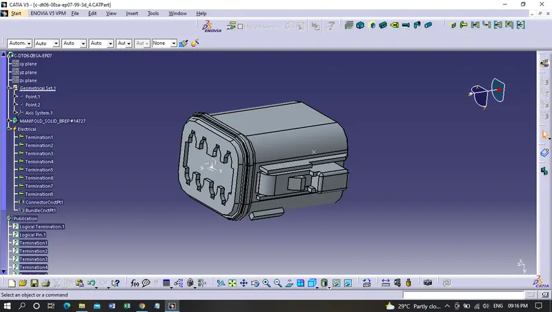
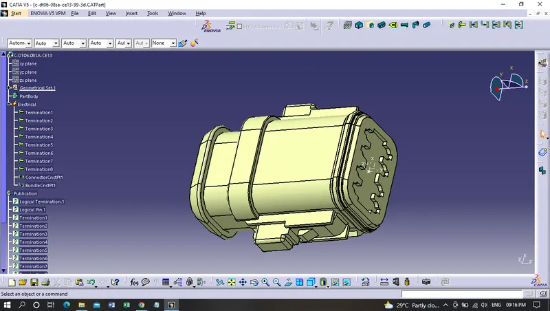
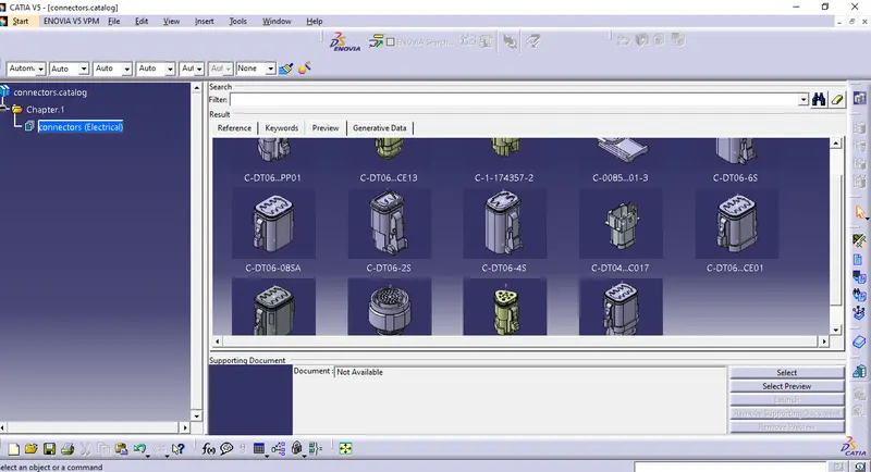
Adding the connectors to the connectors catalog:
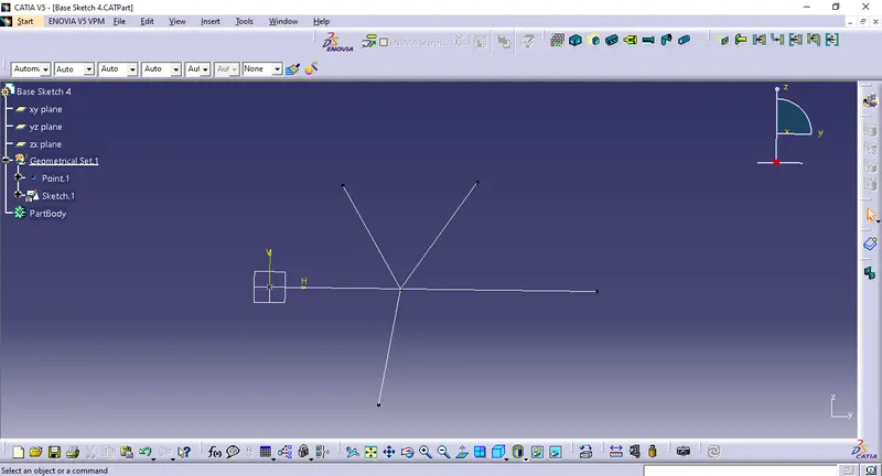
Drawing the base Sketch for harnessing:
Harness_A:

Harness_B:
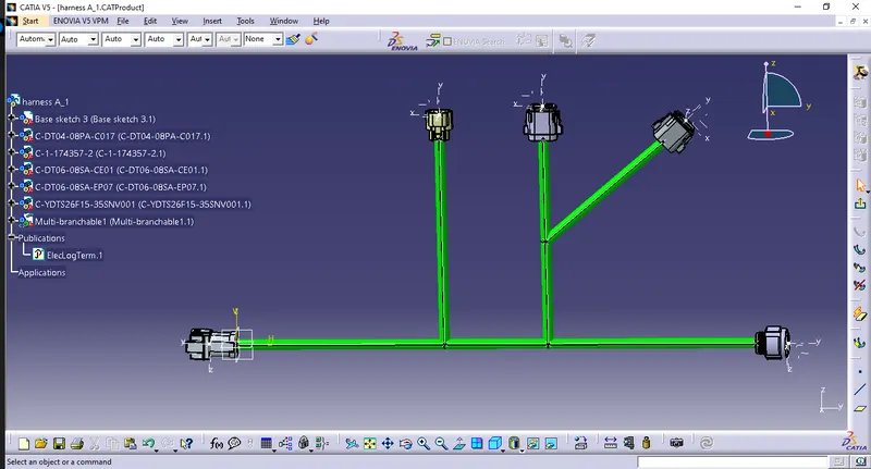
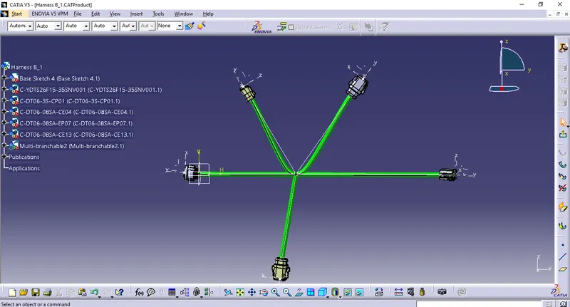
Creating a product file and routing both the harnesses:
Harness_A:
Harness_B:
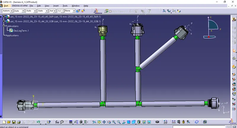
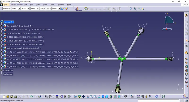
Adding a protective covering to the Harness:
Harnes_A:
Harness_B:
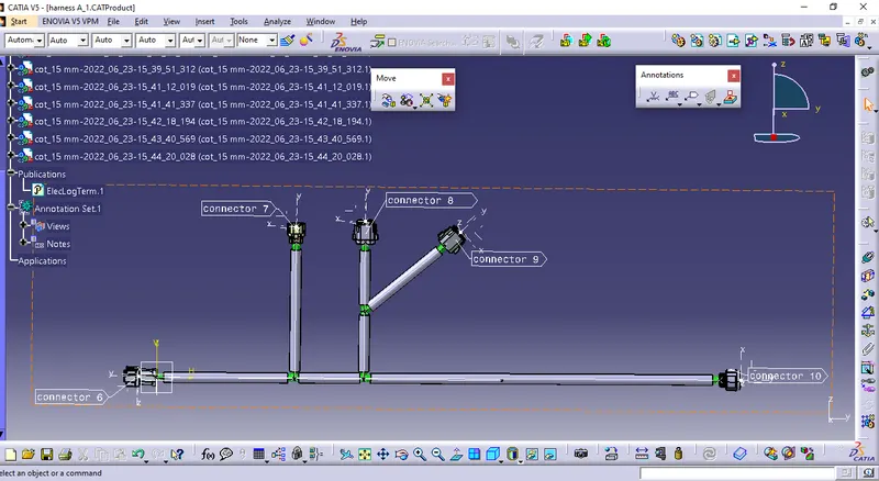
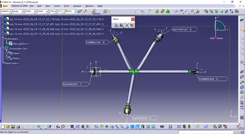
Annotating both the harnesses:
Harness_A:
Harness_B:
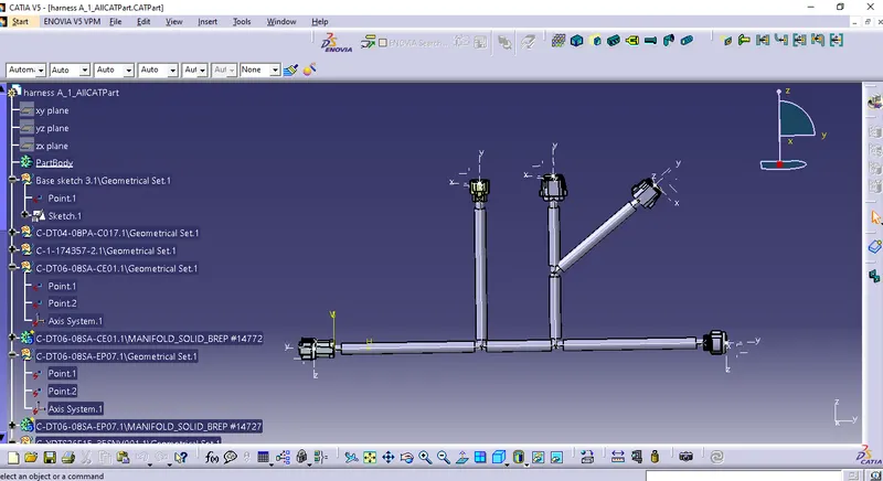
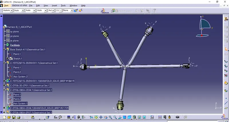
Converting the Files to ALLCATParts:
Harness A:
Harness B:
Joining Both the harnesses and combining them:
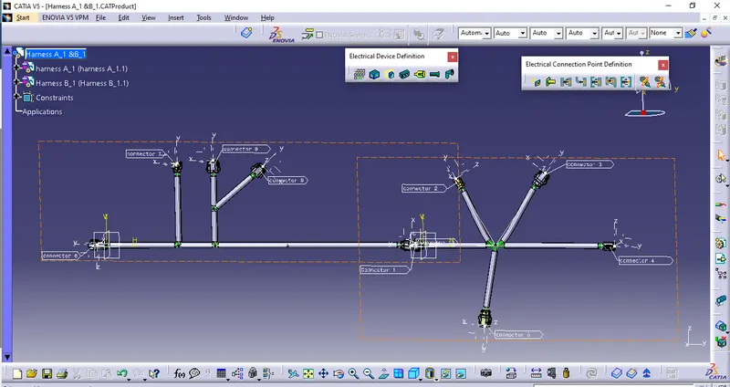
Harness A & B:
Conclusion:
In the above task given the connectors are routed in two different harnesses and then the two harnesses are joined together in a product file as shown above.
Here Different tasks are performed;
- First, the connectors are defined and converted into electrical parts.
- Then a base sketch is drawn for both the harnesses.
- After that, the connectors are placed according to the base sketch, and routing is done.
- protective covering is then added to each harness.
- Then each harness file is converted to an ALLCATPart file.
- And at last both the harnesses are joined together.
********************