Radar Mast & Final Assembly of Yacht
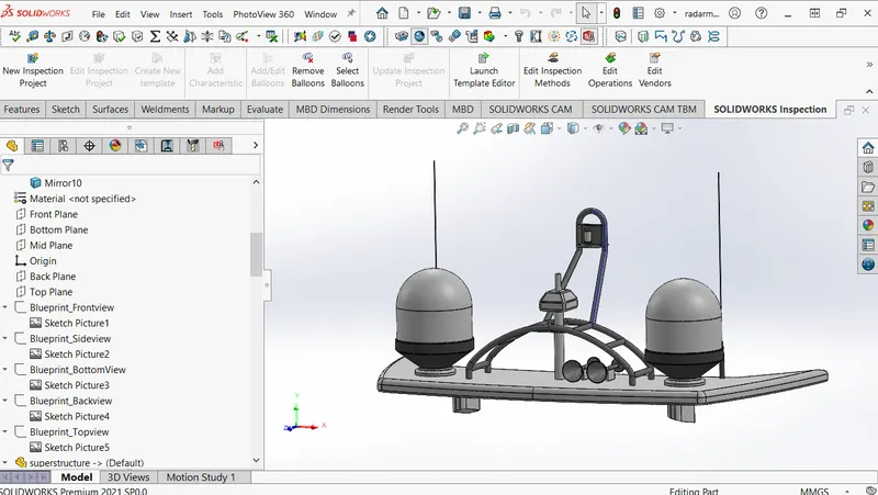
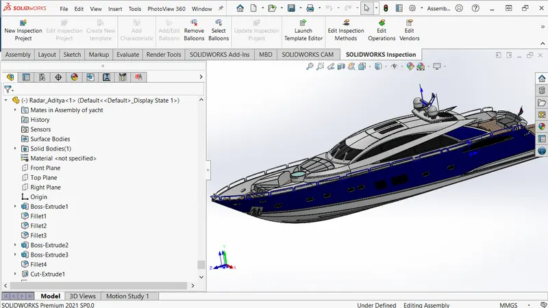
Radar Mast -
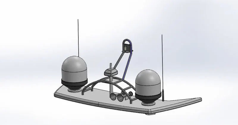
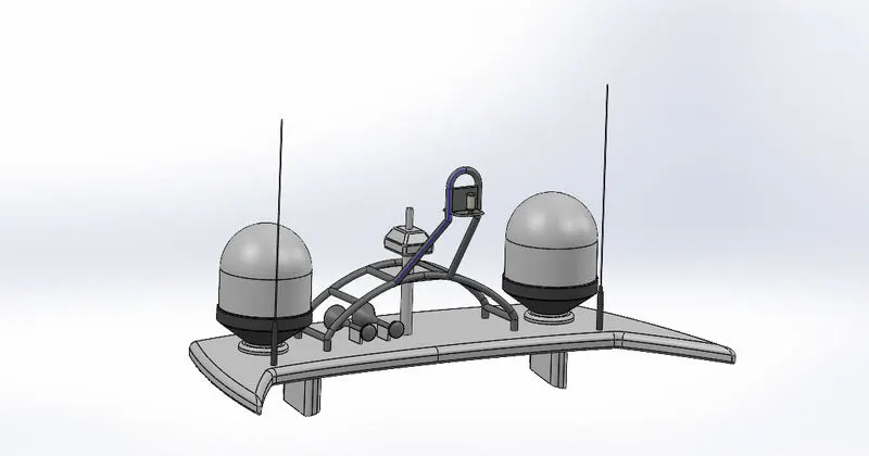
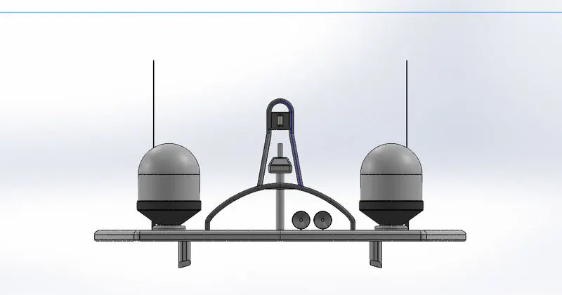
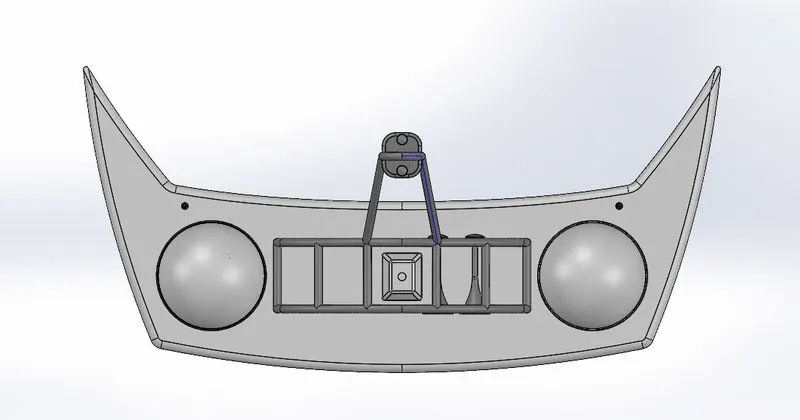
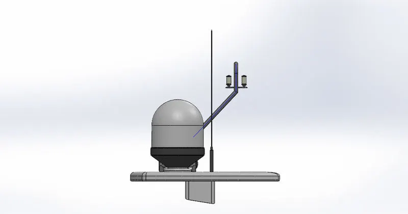
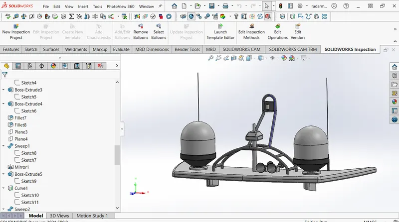
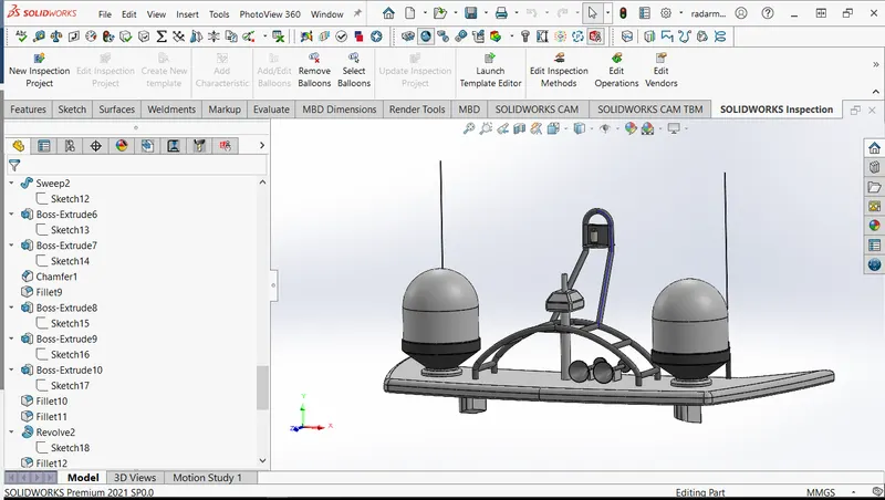
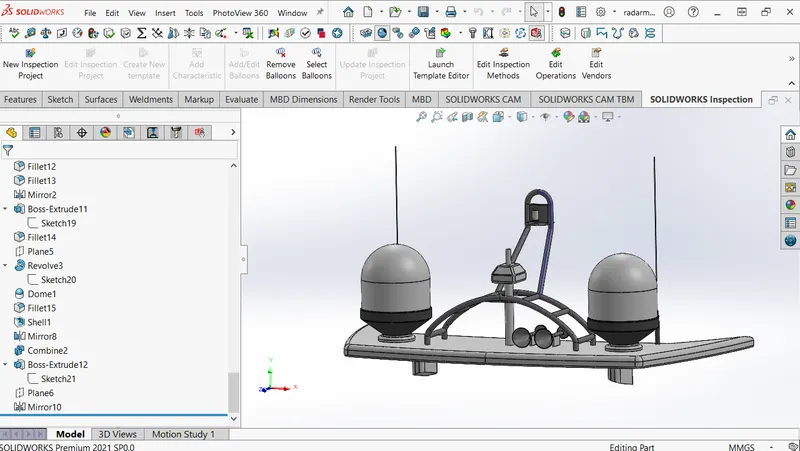
Feature Tree of Radar Mast -
1. 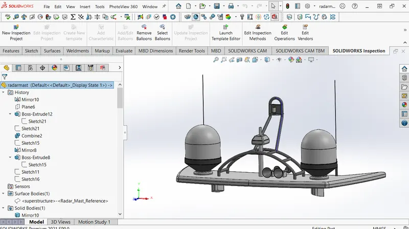 2.
2. 
3. 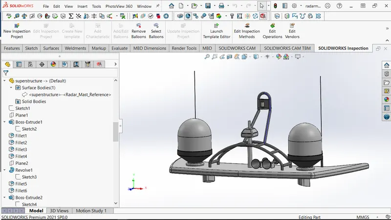 4.
4. 
5.  6.
6. 
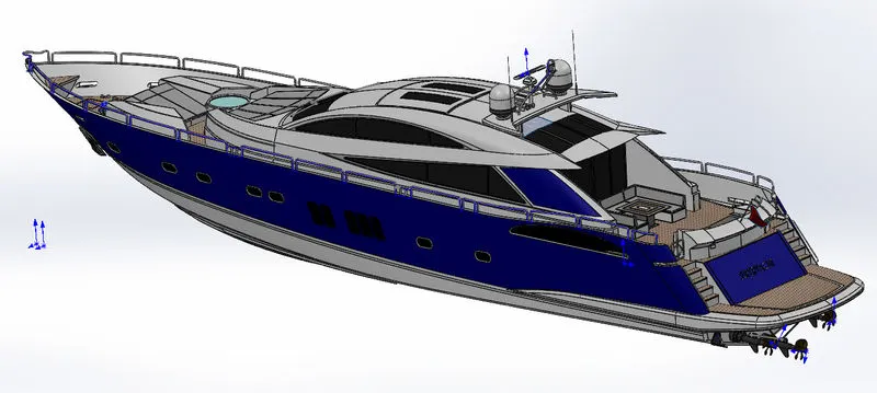
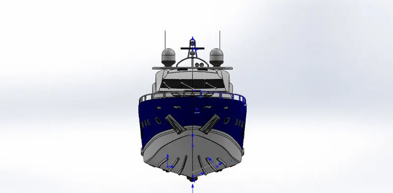
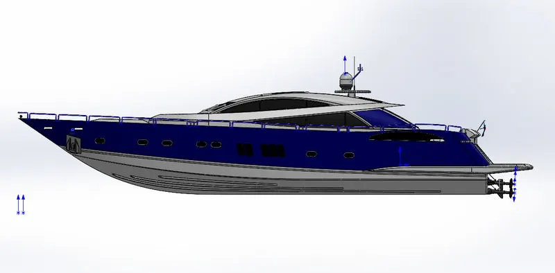
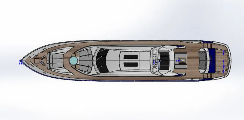
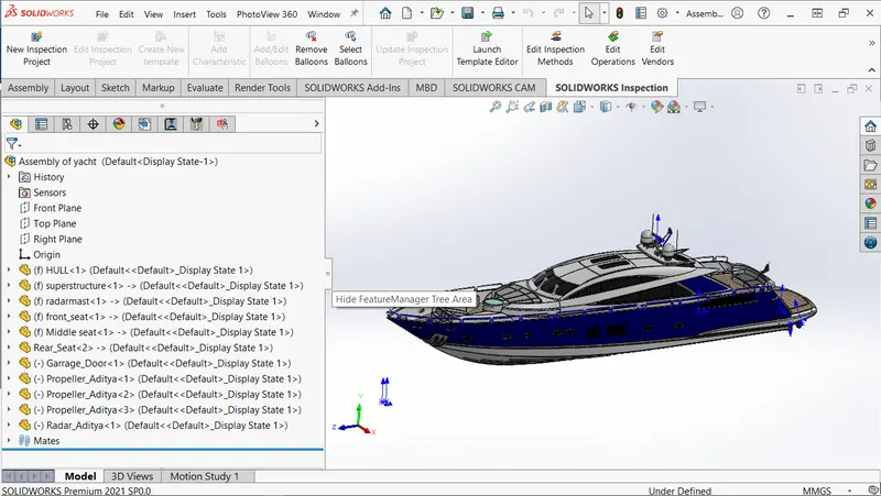
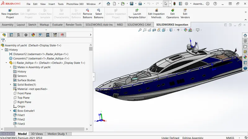
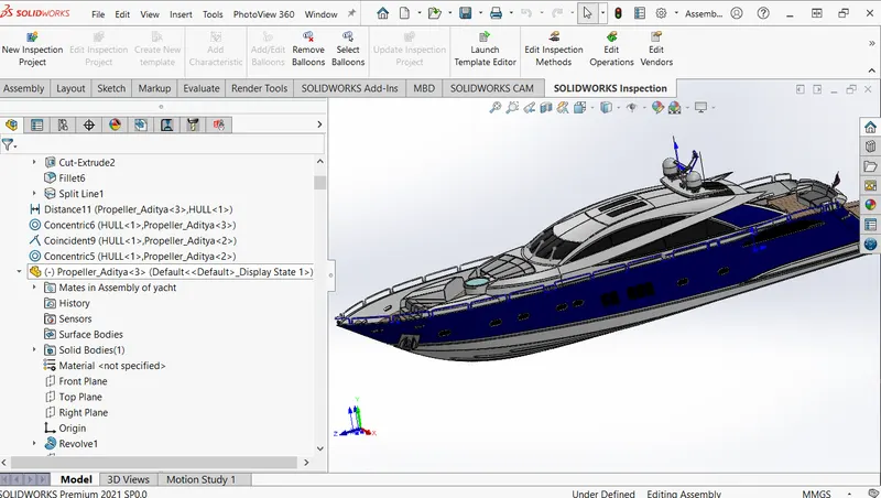
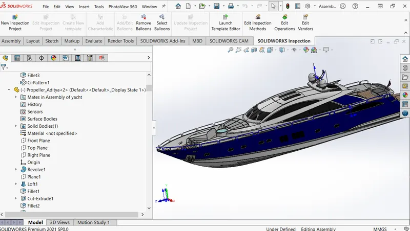
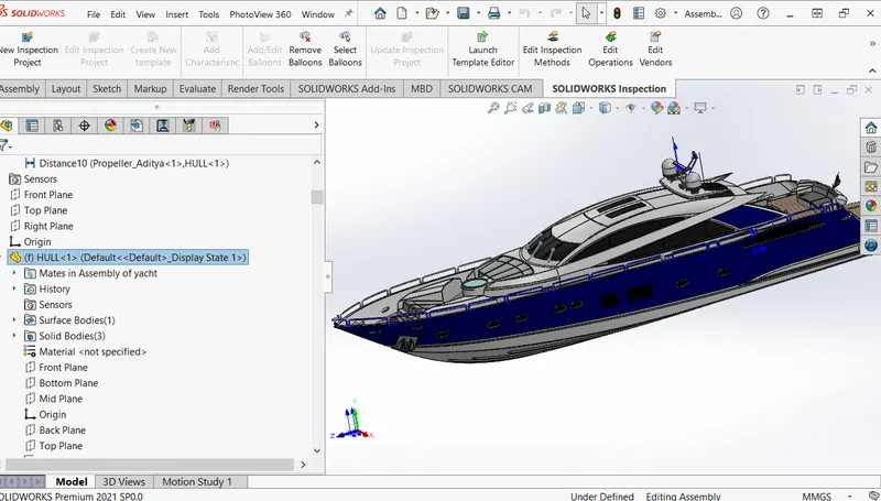
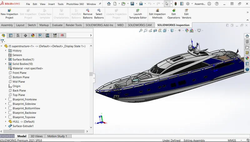
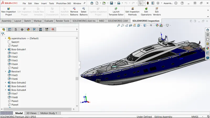
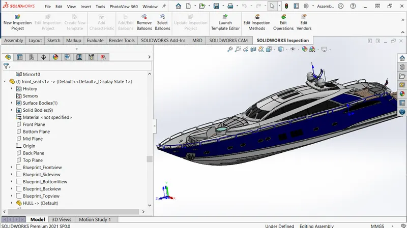
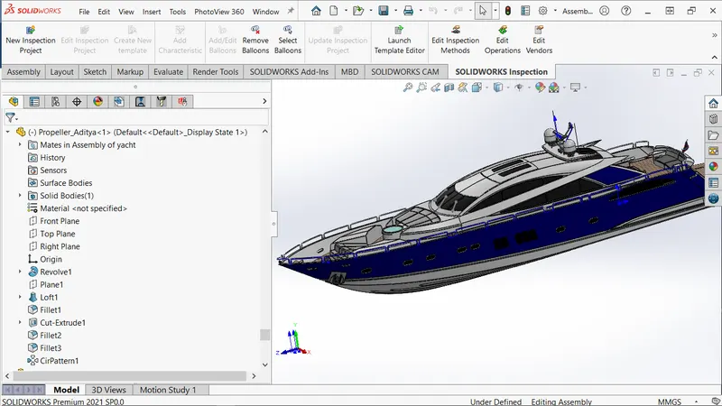
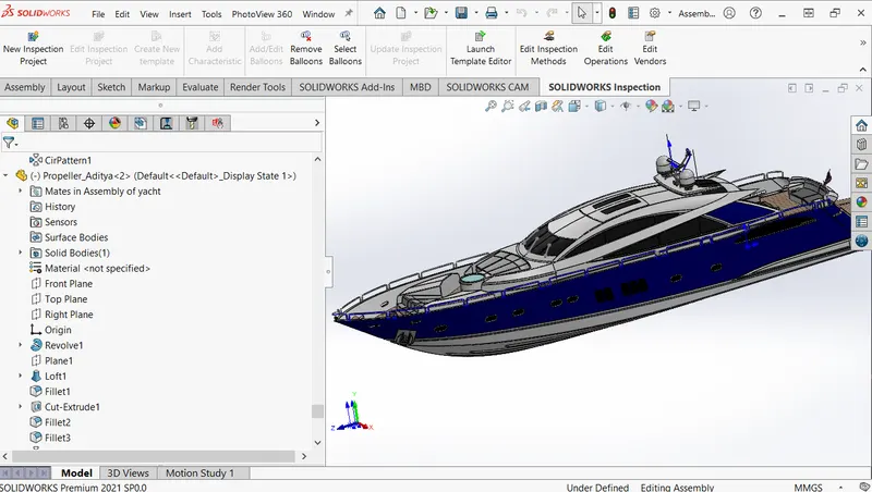
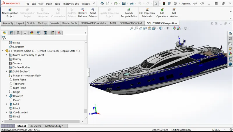
Assembly Of the YACHT -
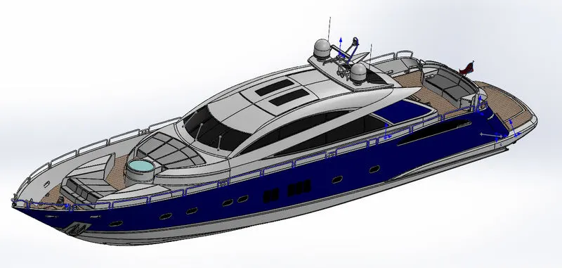
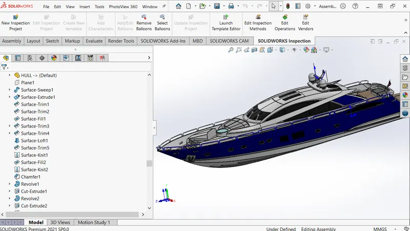
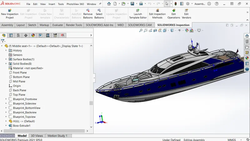
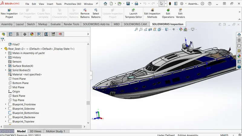
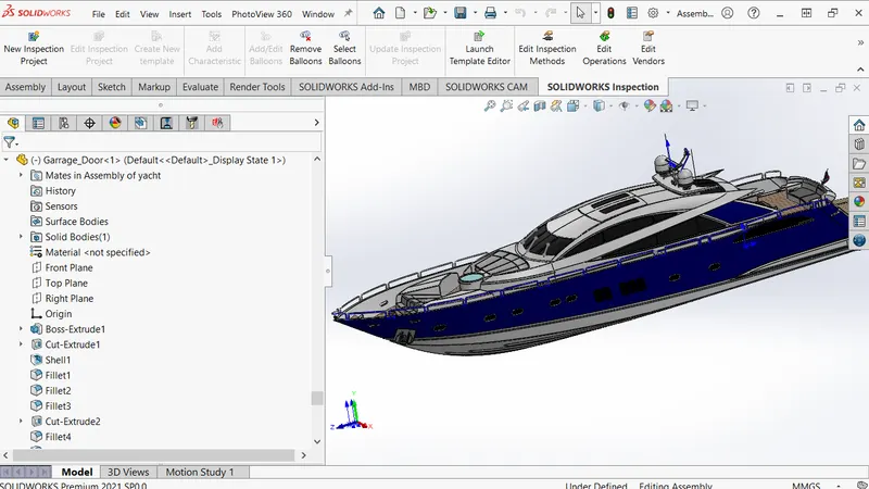
feature tree of the Assembly -
1.  2.
2. 
3.  4.
4. 
5.  6.
6. 
7.  8.
8.
9.  10.
10. 
11.  12.
12. 
13.  14.
14. 
15.  16.
16. 
17. 
Project Report:
Title: Modelling of SUPERYACHT using Solidworks
Objective
To Model, Assemble, and Render the components of SUPER YACHT using 3D cad software SOLIDWORKS.
Introduction
This project report gives an overview of how I modeled the components of the SUPER YACHT and assembled them after modeling it.
As well as I also experimented with the render section by rendering the model components and the final assembly in order to get a realistic view.
Design Methodology
- Modeling of components
- Assembling the components
- Rendering the final 3D Model.
A SUPERYACHT or MEGAYACHT is a large and luxurious pleasure vessel. There are no official or agreed-upon definitions for such YACHTS, but these terms are regularly used to describe professionally crewed motor or sailing yachts, ranging from 40 meters (130 ft) to more than 180 meters (590 ft) in length, and sometimes include yachts as small as 24 meters (79 ft).
So, some of the major Features used for modeling components of the YACHT are as follows: -
- Sketches - 2D sketch,3D sketch
- Planes
- Axis
- Projected Curve
- Sketch Blocks
- Extrude Boss/Base
- Revolved Boss/Base
- Surface extrude
- Lofted Surface
- Lofted Boss/Base
- Split Line
- Fillet
- Chamfer
- Mirror Tool
- Combine
- curve
- Swept Boss/Base
- Surface sweep
- Extruded Cut
- Offset Surface
- Extend Surface
- Shell Tool
- Ruled surface
- Dome
- Linear Pattern
- Curve pattern
- Cut with Surface
- Surface Trim
- Knit
- Delete Face
Components of SuperYacht
The major components modeled of the SUPERYACHT are as follows: -
- Hull
- Superstructure
- Front seat
- Middle seat
- Rear seat
- Garage Door
- Radar Mast
- Radar
- Propeller
Illustration of different components:
Propeller
A propeller is a device with a rotating hub and radiating blades set at a pitch to form a helical spiral that exerts linear thrust upon a working fluid such as water or air when rotated.
In the below design process of the propeller, various features have been used and especially the circular pattern has been used to build the 6 blades.
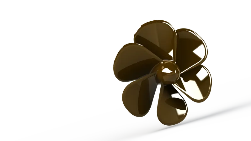
Features applied here are:
- Revolve
- Loft
- Fillet
- Cut- Extrude
- Circular Pattern
- Reference Plane
- Appearances
Radar
A device used for detecting other ships and land obstacles, to give bearing and distance for collision avoidance and navigation while on water.
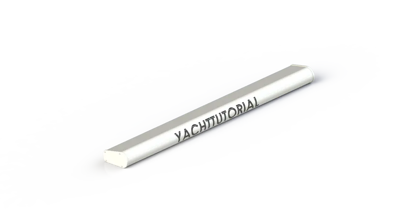
Features applied to build this are:
- Boss Extrude
- Fillet
- Cut- Extrude
- Sketch pattern
- Mirror
- Split line
- Appearances
Front Seat
In the design process of the front seat, various features have been used to build it beautifully and rendering has been done to give it a realistic view.
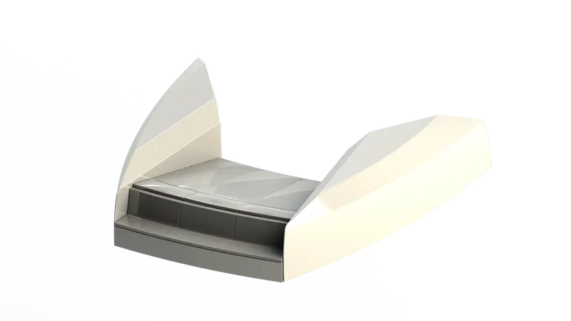
Features applied here are:
- Boss extrude
- Cut Extrude
- cut-Extrude Thin
- Revolve
- Chamfer
- Fillet
- Mirror
- Dome
- Surface Loft
- Surface Trim
- Surface Fill
- Surface Knit
- Appearances
Middle seat
just like the design process of the front seat, the Middle seat has been created in the same way with the help of various features.
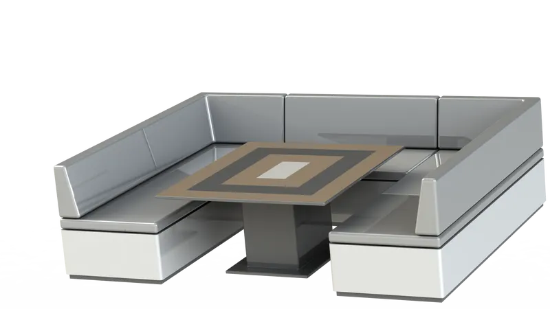
Features applied here are:
- Boss Extrude
- Cut Extrude
- Fillet
- Chamfer
- Mirror
- Appearances
Rear Seat
A complex design process was created with the help of various features.
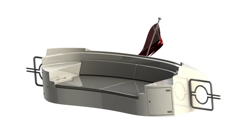
Features applied here are:
- Reference Plane
- Surface Sweep
- Surface Offset
- Surface Trim
- Ruled Surface
- Surface Knit
- Surface Extend
- Boss Extrude
- Sweep
- Cut- Extrude
- Sweep
- Chamfer
- Fillet
- Mirror
- Appearances
Garage Door
Another part of the yacht has been build using different features.
Features applied here are:
- Boss Extrude
- Cut Extrude
- Shell
- Fillet
- Mirror
- Appearances
Hull
Hull is the base of the SUPERYACHT which contains all the necessary elements to run a Yacht, especially an Engine. It is the most complex part of the Yacht as it consists of a lot of challenges to trigger with different types of sketches and features.
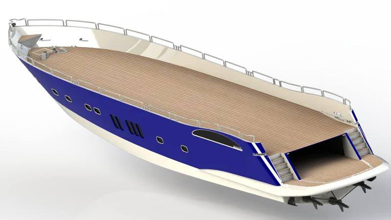
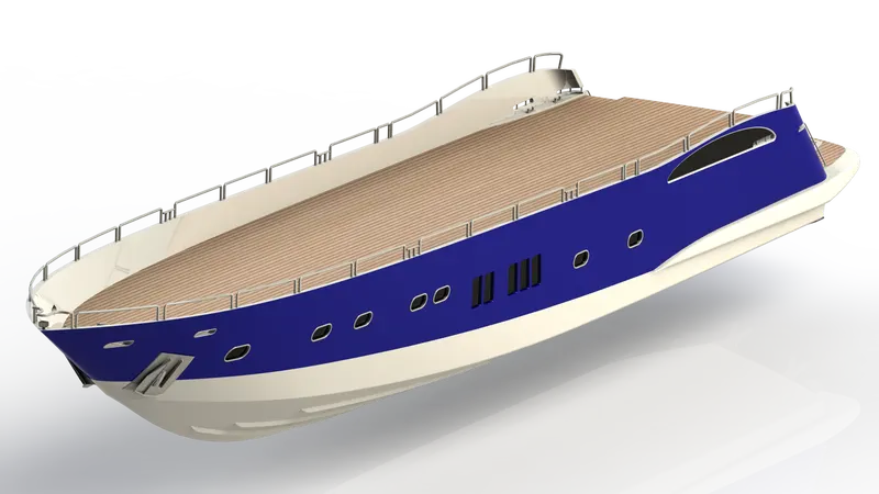
Features Applied here are:
- Curve
- Surface Loft
- Surface trim
- Mirror
- Cut Extrude
- Deck surface
- Split line
- Boss Extrude
- Surface Extrude
- Surface Knit
- Surface Fill
- Shell
- Fillet
- Chamfer
- Reference Plane
- Sweep
- Revolve
- Dome
- Helix Spiral
- Linear Pattern
- Combine
- Pattern Direction
- Cut Extrude Thin
- Appearances
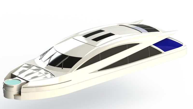
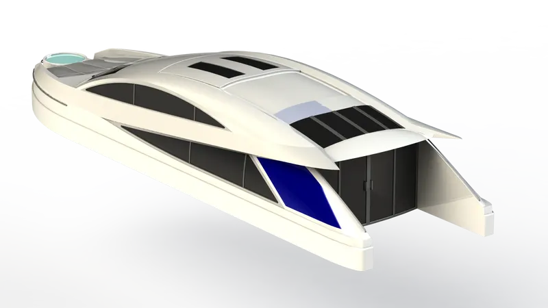
Superstructure
Just like the Hull, the most essential and critical part of the Yacht controls the movement and other activities held inside it. It also contains a complex design ending with a beautiful structure.
Features applied here are:
- Surface Sweep
- Surface Knit
- Fillet
- Ruled Surface
- Surface Trim
- Curve
- Surface loft
- Delete Face
- Surface Extrude
- Boss Extrude
- Cut Extrude
- Fillet
- surface Offset
- Thicken
- Dome
- Reference Plane
- Split line
- Extrude Thin
- Mirror
- Chamfer
- Appearances
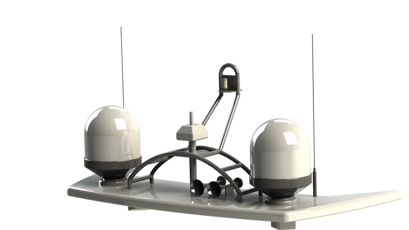
Radar mast
An Electronic device used to navigate ships, communicate, find other ships, and land obstacles.
Features applied here are:
- Reference Plane
- Boss extrude
- Fillet
- Revolve
- Sweep
- Mirror
- Curve
- Chamfer
- Combine
- Shell
- Dome
- Appearances
Assembly
Assembly modeling is a technique applied by CAD and product visualization software systems to utilize multiple files that show components within a product. The components within an assembly are called solid / surface models.
Different Types of Approaches in Assembly:
- Bottom-Up Approach
- Top-Down Approach
SUPERYACHT Assembly:
After the modeling of different components of the superyacht, along with the main body, all other parts are assembled using different relations.
The relations applied here are:
- Distance
- Concentric
- Coincident
Rendering
Rendering is the process involved in the generation of a two-dimensional or three-dimensional image from a model using application programs. Rendering helps increase efficiency and reduce cost in design.
Categories:
- Integrated Preview
- Preview Render
- Render region
- Final/Real Render
Software used:
- Photo View 360
- Solid Works Visualize
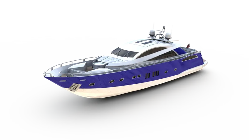
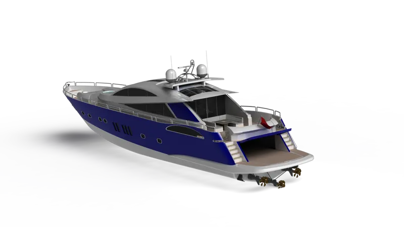
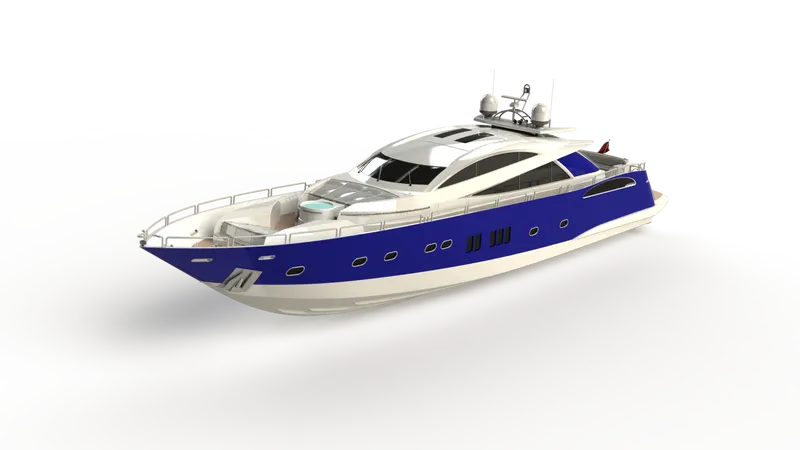
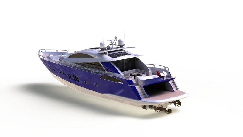
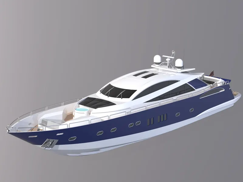
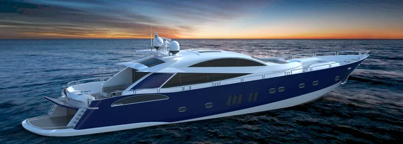
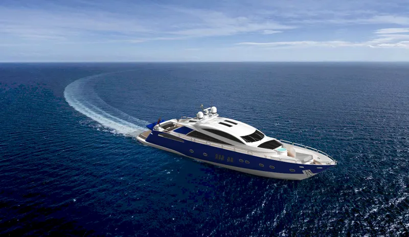
Rendering of The Superyacht:
Conclusion:
In this project, the various parts of the SUPERYACHT were modeled in the different Environments like Surface modeling, Solid Modeling, and Assembly available in the Solid works.
The assembly of the SUPERYACHT and the different parts of the YACHT are finally rendered with Photo-view 360 and Solid works Visualize to create a realistic view of the model with the environment and also to show a detailed finish in each and every part.
Designing, modeling, and rendering this magnificent machine was an incredibly great experience.
GOOGLE DRIVE LINK-
https://drive.google.com/drive/folders/1YmHu2Sl8vEGiJ8NyAcSTkWjtsNSRDcq9?usp=sharing
************