Photo Realistic Rendering
TITLE- MODELLING OF AMERICAN CHOPPER USING SOLIDWORKS
Objective
To Model, Assemble, and Render the components of American Chopper using 3D cad software SOLIDWORKS.
Introduction
This project report gives an overview of how I modeled the components of the American chopper and assembled them after modeling it.
As well as I also experimented with the render section by rendering the model components and the final assembly in order to get a realistic view.
Design Methodology
- Modelling of components
- Assembling the components
- Rendering the final 3D Model.
The American Chopper is a type of custom motorcycle which employs radically modified steering angles and lengthened forks for a stretched-out appearance. They can be built from an original motorcycle that is modified ("chopped") or built from scratch which is its specialty.
So, some of the major Features used for modeling components of the chopper are as follows: -
- Sketches
- Planes
- Axis
- Projected Curve
- Sketch Blocks
- Extrude Boss/Base
- Revolved Boss/Base
- Surface extrude
- Lofted Surface
- Lofted Boss/Base
- Split Line
- Fillet
- Chamfer
- Mirror Tool
- Combine
- curve
- Swept Boss/Base
- Surface sweep
- Extruded Cut
- Offset Surface
- Shell Tool
- Body-Move/Copy
- Dome
- Linear Pattern
- Circular Pattern
- Curve pattern
- Cut with Surface
- Surface Trim
- Knit
Components of American Chopper
The major components modeled of the American Chopper are as follows: -
- Chassis
- Engine
- Pedal
- Kickstand
- Transmission Belt
- Oil Tank
- Rear Wheel
- Rear Fender
- Chain
- Gas Tank
- Front Fork
- Front Wheel
- Front Fender
Illustration of different components:
Chassis
The chassis is the mainframe of the whole bike as it bears most of the load of different parts aligned to it.
In the below design process chassis, various features have been used in order to build it, and specifically, the mirror tool is used as the lower tube is mirrored concerning the mid-plane to complete the lower end.
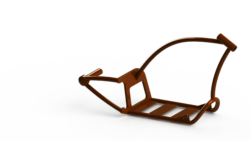
Features applied here are:
- Boss Extrude
- Revolve Boss
- Trim Entities
- Fillet
- Split
- Dome
- Cut Extrude
- Sweep Boss
- Move/Copy Bodies
- Mirror tool
- Appearances
Engine
The most complex design i.e. the heart of the bike known as the engine is covered up with the two exhaust pipes, cooling fins, spark plug representation, transmission unit with the transmission belt, and pulleys.
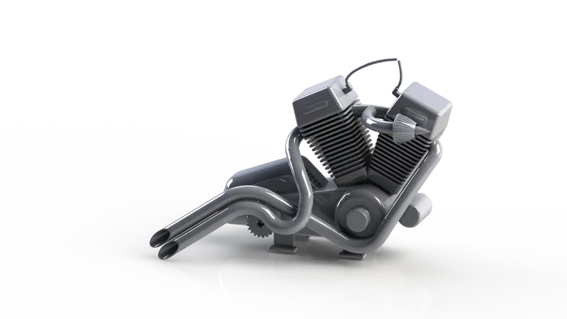
Features applied here are:
- Boss Extrude
- Fillet
- Revolve
- Reference Plane
- Circular pattern
- Dome
- Cut-Extrude
- Chamfer
- Linear Pattern
- Mirror
- Sweep
- Combine
- Curve
- split
Pedal
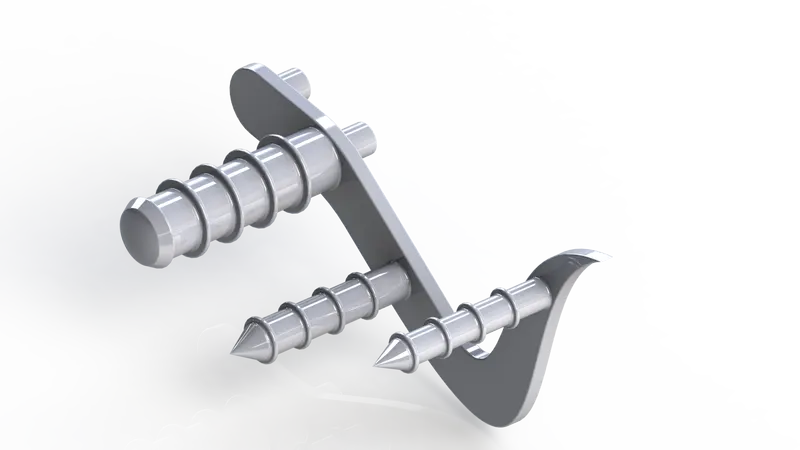
Features applied here are:
- Boss Extrude
- Fillet
- Revolve
- Dome
- Chamfer
- Linear Pattern
- Appearances
Kickstand
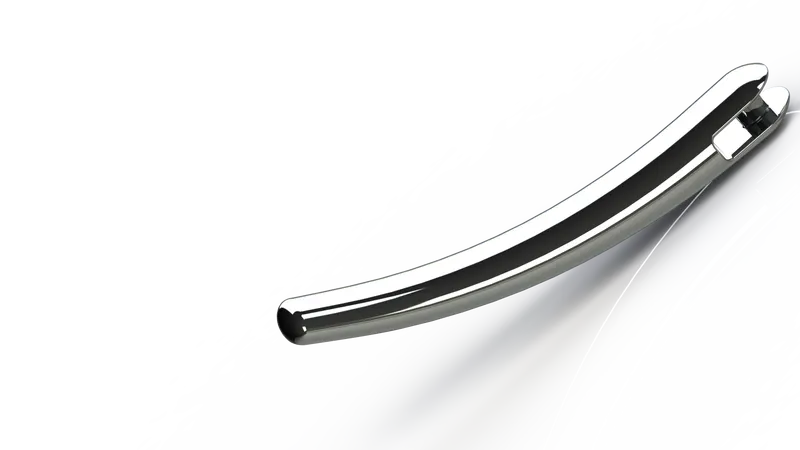
Features applied here are:
- Reference Plane
- Loft
- Dome
- Cut-Extrude
- Split
- Boss Extrude
- Fillet
Transmission Belt
The transmission Belt is a simple design built to control the pulleys fitted in the engine.
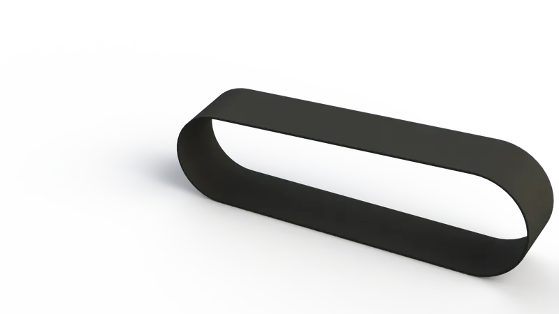
Features applied here are:
- Boss Extrude
- Fillet
- Appearance
Oil Tank
The Oil Tank placed over the engine block is a very simple design built especially to showcase the shell feature.
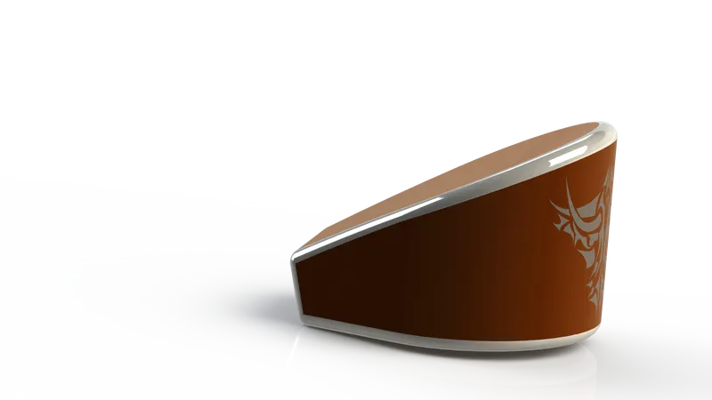
Features applied here are:
- Boss Extrude
- Combine
- Fillet
- Shell
- Appearances
Rear Wheel
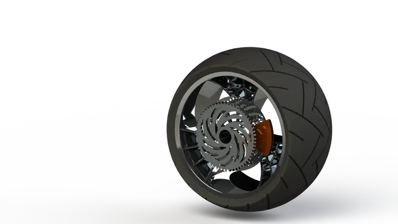
Features applied here are:
- Revolve
- Boss Extrude
- Cut-Extrude
- Circular pattern
- Combine
- Cut-Revolve
- Fillet
- Chamfer
- Appearances
Rear Fender
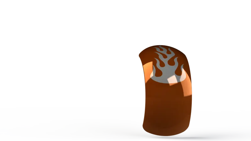
Features applied here are:
- Revolve
- Split
- Fillet
- Shell
- Appearances
Chain
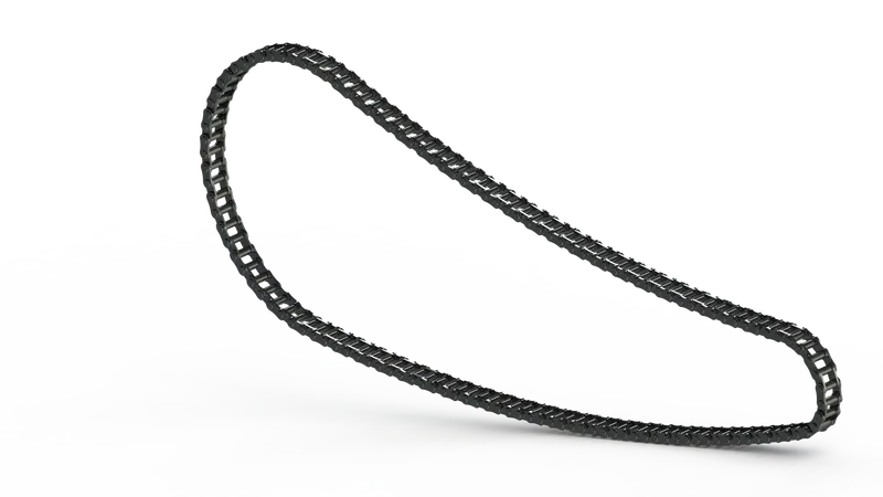
Features applied here are:
- Boss Extrude
- Fillet
- Curve Pattern
- Body-Delete/Keep
- Mirror
- Appearances
Gas Tank
The Gas tank also embeds a complex design of the whole design process as it includes a lot of spline in the sketch and different kinds of features which includes boundary surface, knit surface, extrudes surface, as well as decals, has been also added to the tank to give different look to it.
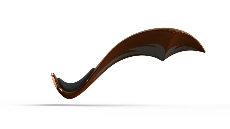
Features applied here are:
- Reference Plane
- Surface Sweep
- Surface trim
- Curve
- Surface Loft
- Boundary Surface
- Mirror
- Surface knit
- Split
- Surface Extrude
- Fillet
- Cut Sweep
- Shell
- Appearances
Front Fork
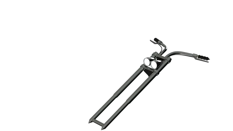
Features Applied here are:
- Revolve
- Boss Extrude
- Fillet
- Linear Pattern
- Cut-Extrude
- Dome
- Cut-Revolve
- Body-Move/copy
- Curve
- Sweep
- Reference Plane
- Combine
- Appearances
Front Wheel
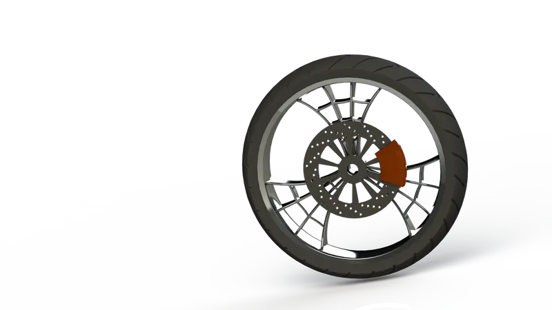
Features applied here are:
- Revolve
- Boss Extrude
- Cut-Extrude
- Cut-Revolve
- Circular Pattern
- Combine
- Fillet
- Chamfer
- Appearances
Front Fender
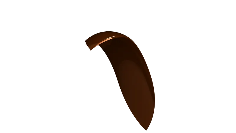
Features applied here are:
- Revolve
- Split
- Fillet
- Appearances
Assembly
Assembly modeling is a technique applied by CAD and product visualization software systems to utilize multiple files that show components within a product. The components within an assembly are called solid / surface models.
Different Types of Approaches in Assembly:
- Bottom-Up Approach
- Top-Down Approach
American Chopper Assembly:
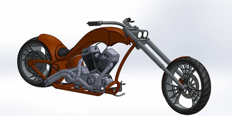
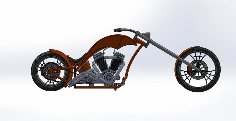
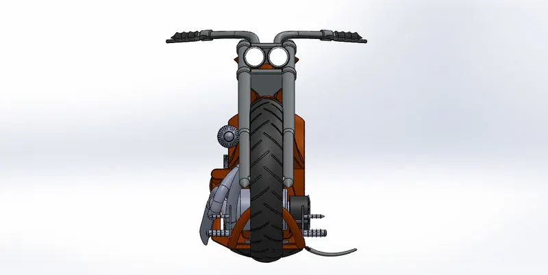
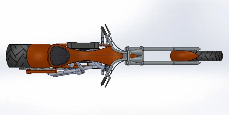
After completing the modeling of different parts, the main body (Chassis and Engine with all parts) is inserted into the assembly environment and assembled into a beautiful chopper using various relations. Some of the relations are:
- Coincident
- Concentric
- Parallel
- Tangent
- Width
- Angle
- Tangent
- Distance
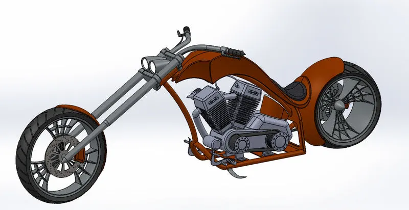
(ISOMETRIC VIEW)
Rendering
Rendering is the process involved in the generation of a two-dimensional or three-dimensional image from a model using application programs. Rendering helps increase efficiency and reduce cost in design.
Categories:
- Integrated Preview
- Preview Render
- Render region
- Final/Real Render
Software used:
- Photo View 360
- Solid Works Visualize
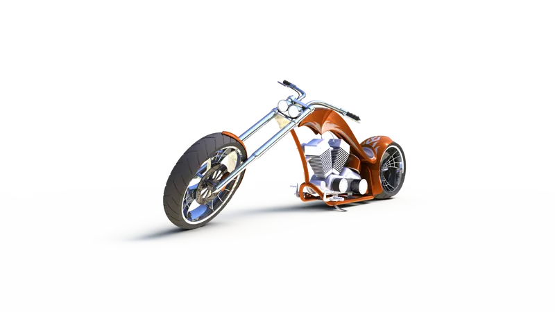
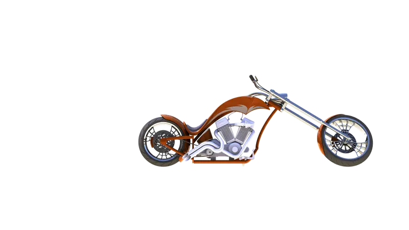
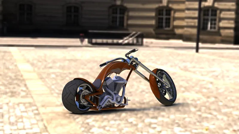
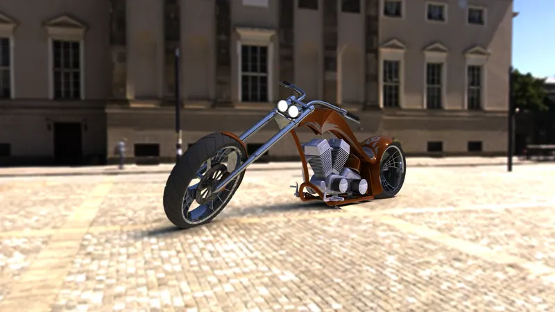
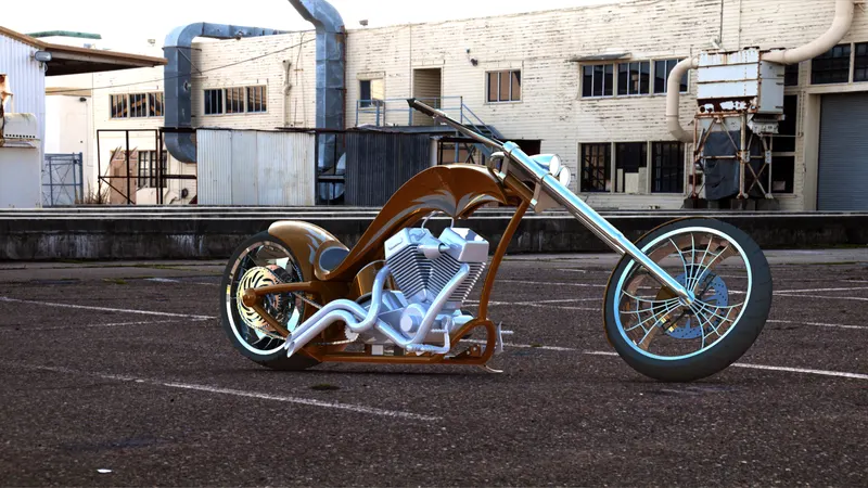
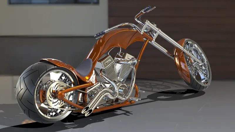
Rendering of the American Chopper:
Conclusion:
In this project, the various parts of the American Chopper were modeled in the different Environments Surface modeling, Solid Modeling, and Assembly available in the Solid works.
The assembly of the American Chopper and the different parts of the American chopper are finally rendered with Photo view 360 and Solid works Visualize to create a realistic view of the model with the environment.
GOOGLE DRIVE LINK-
https://drive.google.com/drive/folders/1YmHu2Sl8vEGiJ8NyAcSTkWjtsNSRDcq9?usp=sharing
*******************