Project 1
Aim: To route the Wiring harness on the given engine and prepare a flatten view drawing in CATIA V5. The application of all Packaging rules, Industry best practices studied in this course will be demonstrated in design. As well as Protection coverings to be added if required.
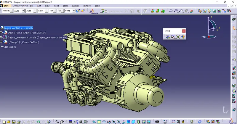
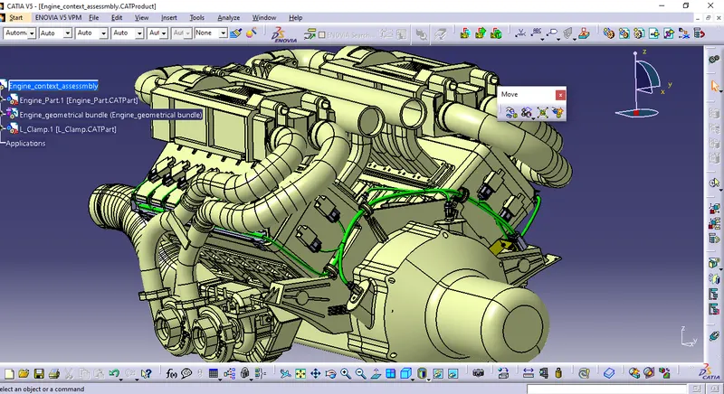
The Engine to be harnessed is:
V-16 Engine
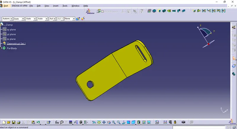
L-CLAMP (reference for the placing of the interconnector in the engine to start the routing)
Sensors Required to fit in the engine for harnessing are:
- 16 injector sensor
- 1 Coolant sensor
- 1 Speed sensor
- 1 Neutral sensor
Starting with the process
First, a context assembly was created in the product file in which the reference engine was added as shown in the above picture. Additionally, an L-clamp was added as a reference to be fitted in the engine for the connectors to be placed.
After that, another product file was created in the same context assembly named Engine Geometrical Bundle where all the electrical parts were to be added for further harness proceedings.
Coming to all the sensors that were mechanical parts, it was defined through points and axis and converted into electrical parts by giving a connector connection point as well as a bundle connection point.
Sensors converted into electrical parts are:
C-1563689-1
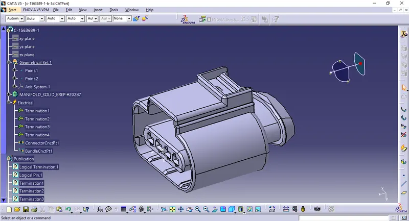
C-282080-1
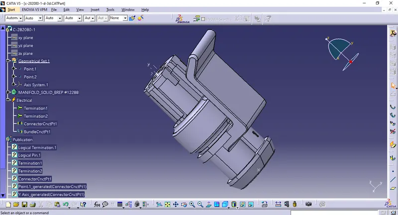
C-776438-4
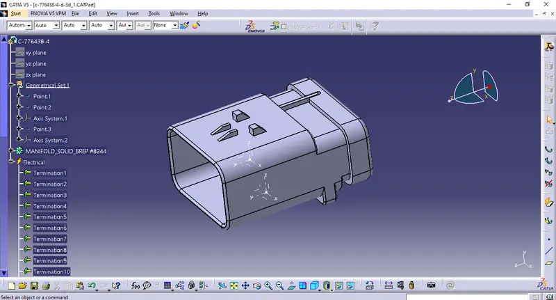
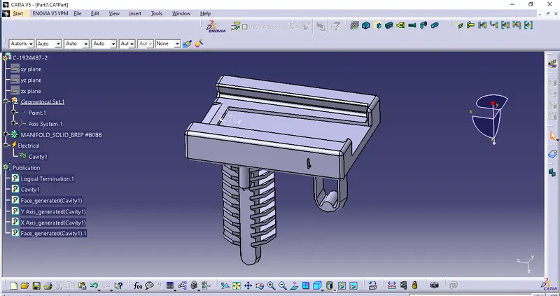
Part defined as Cavity and mounting Equipment:
C-1924487-2
Here the part is defined as a piece of mounting equipment and then a cavity is defined so that the above-shown interconnector can fix into it through a cavity connection point defined in it.
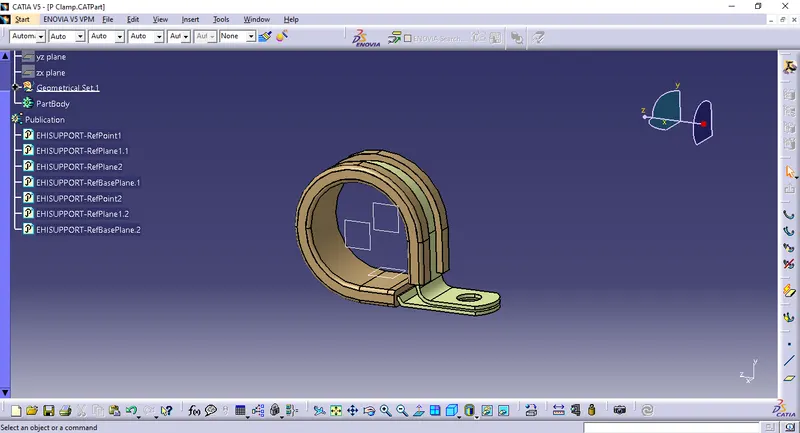
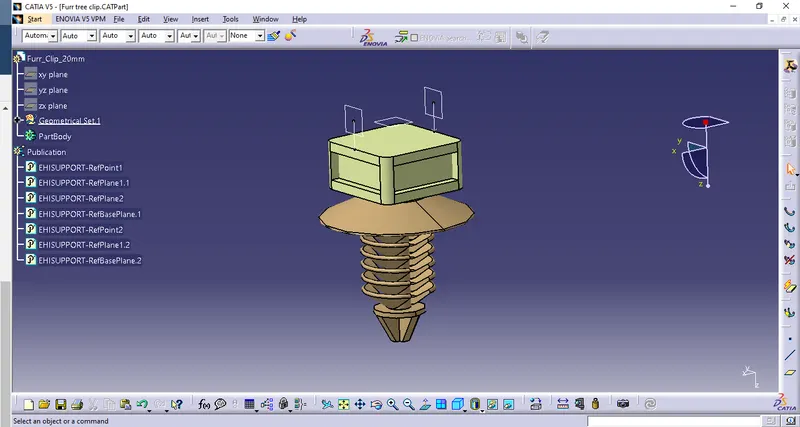
Parts defined as a support for the bundle routing:
- P-Clamp
- Furr tree Clip
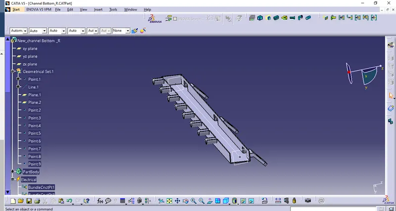
Guiding Channel Defined as an electrical component(Equipment):
- This is because while flattening if the guiding channel wouldn't be converted into an electrical part it wouldn't have been able to display there as well as the routing also wouldn't have been possible.
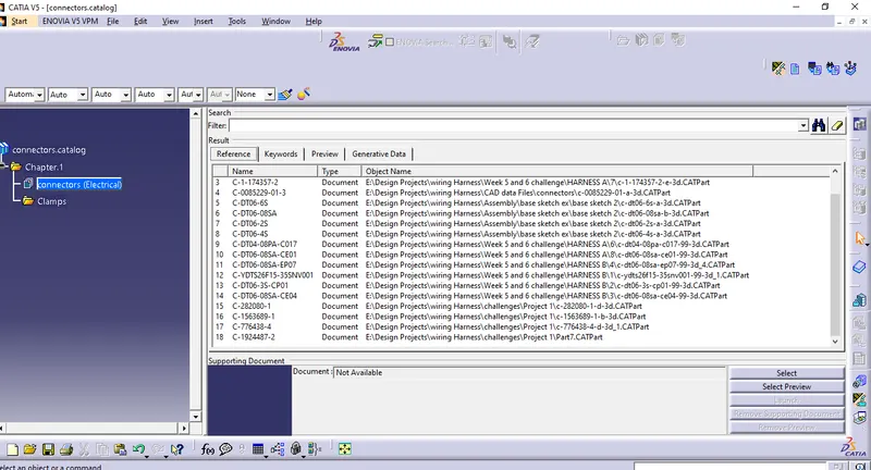
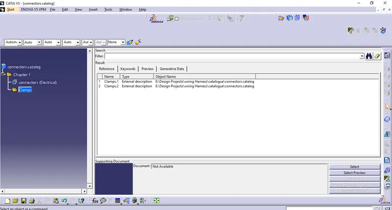
Adding the Connectors and clamps to the catalog:
After defining and converting all the required parts, the sensors and clamps were placed in their respective positions in the provided reference engine(V-16) for a smooth routing process.
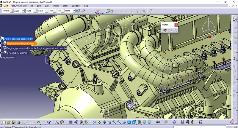
Starting with the Harness procedure, first of all, the product file was opened in the Electrical harness assembly workbench and a geometrical bundle was added to the Engine Geometrical bundle.
This led to the initialization of the harnessing and the harnessing was done by selecting each component present over there. None of the points were selected for the routing because it would have created a Flattening error while flattening the Bundle segment in the future (i.e. while flattening the components it wouldn't have been visible if they were not selected during the routing process was going on).
- Visualization Mode
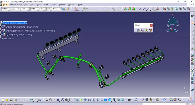
- Design Mode
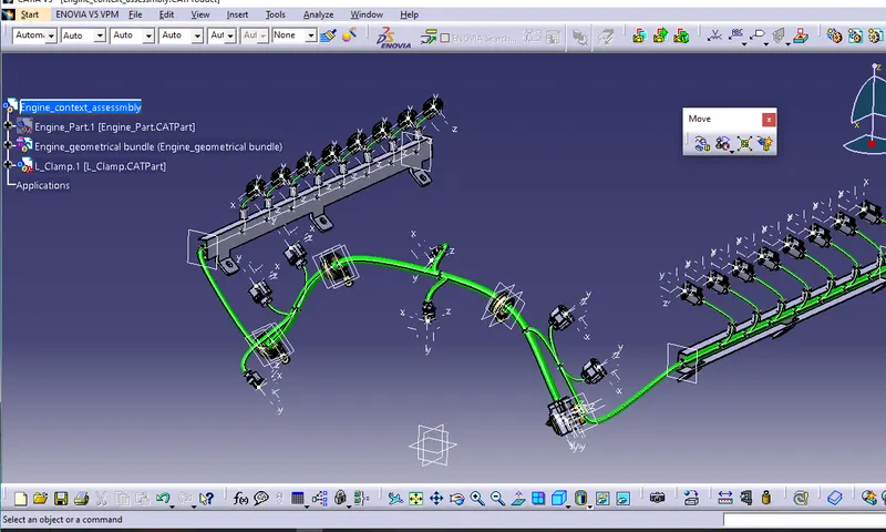
- So in the above harness, Various branch points were added which had a minimum distance of 50mm from each connector or clamp for a Clean, better, and error-free routing.
- Each branch point can have a maximum division of 4 BUNDLE SEGMENTS.
After the completion of routing, the Flattening procedure starts:
In this Flattening procedure at first, the Electrical Harness Flattening workbench is opened, and flattening parameters are added.
Then the extraction of the Enigne Geometrical bundle is done and flattened using the flatten toolbar.
- Design Mode
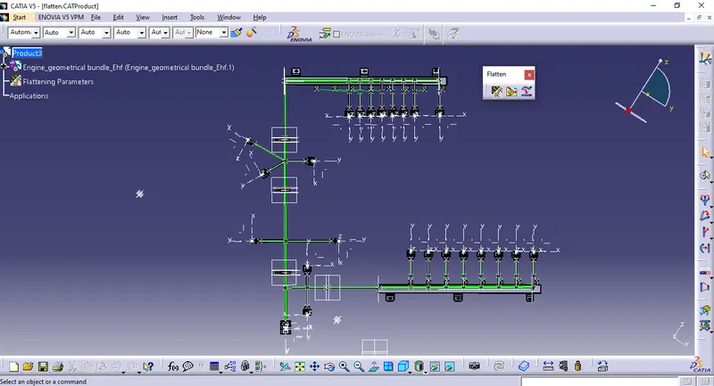
- Visualization Mode
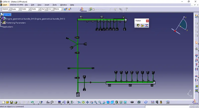
As shown in the above figure, in the flattening of all the bundle segments that were misaligned, are aligned to a particular direction and angle through a toolbar called ROTATE for a better Drawing view.
Coming to the last stage of the ENGINE HARNESSING - 2D Drawing:
In this stage, a drawing workbench is opened, and then using the front view toolbar the extraction of the 2D Drawing is done from the flattened file.
- 2D Drawing
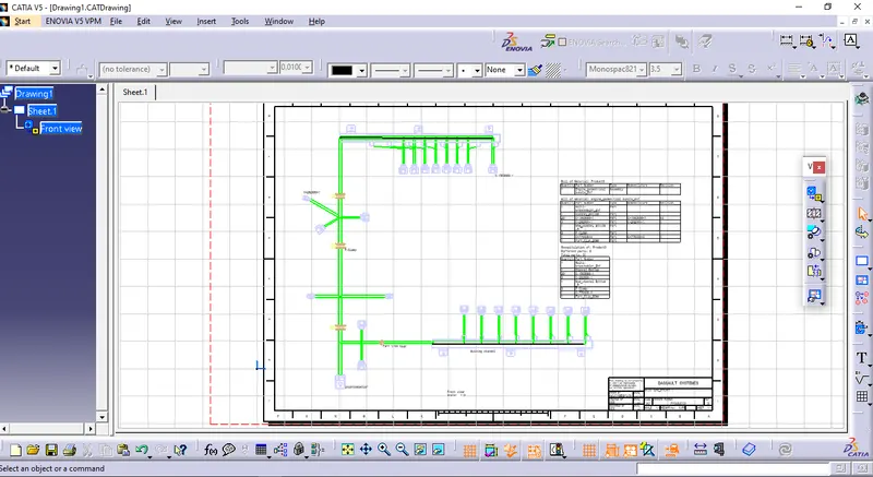
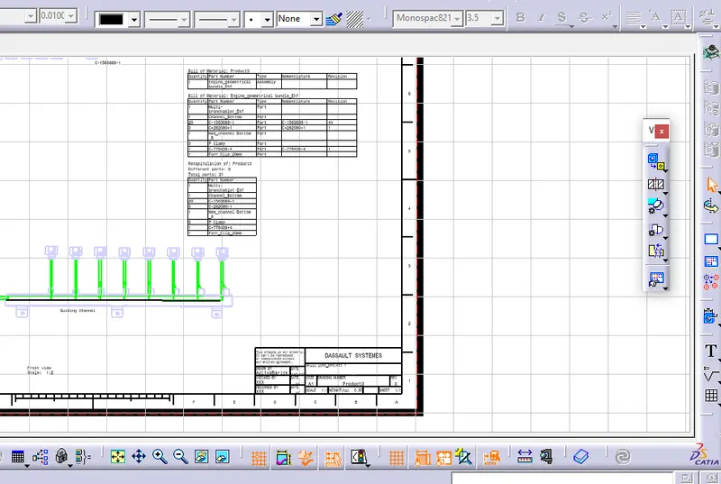
- In order to give a brief description of the flattened image and the Sheet used to display the image, the template, and Bill of Materials are added to the 2D drawing for better clarification.
Conclusion:
In this above V-16 Engine Harness a lot of functions were used to make this structure possible, they are:
Mechanical Part design workbench- Here the parts were defined using the point, plane, line, and axis system.
Electrical Part design workbench - Here the parts were electrically defined, connector connection point - Bundle connection point - cavity connection point, etc were also added.
Mechanical assembly design - In this workbench, the alignment of the parts was done using the manipulation toolbar, snap, and smart move feature.
Electrical Assembly design - Here the electrical parts were connected to each other.
Electrical harness assembly - In this workbench, the routing of the bundle segments was done from each connector instead of the points so that they could be visible while Flattening the routing.
Electrical harness Flattening - The routing done is flattened in order to get a 2D drawing out of it.
After completing this process a major role is played by the save management toolbar as it propagates all the connectors, branches, and reference part files to a single folder to save it from a mismatch.
****************************