Wiring harness design in CATIA V5 - 3D modeling Week 4 Challenge
WEEK-4_CHALLENGE_ WIRING HARNESS DESING IN CATIA V5_3D MODELING
OBJECTIVE:
To creating the routing from the given harness layout in Electrical workbench by using CATIA v5_ 3D modeling.
GIVEN DATA:
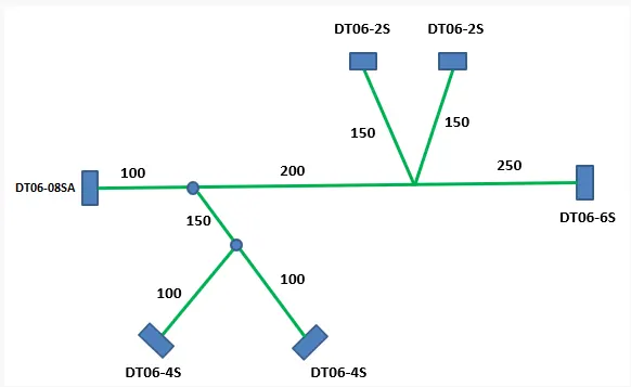
INPUTS & ASSUMPSTIONS:
Assume thus the Bundle diameter are following as,
Main Branch Bundle dia as 15mm, And
Sub Branches may assumed as following 10 mm and 5 mm are used to creating the given routing.
And then given Connectors and its required quantity from the given layout are following as,
S.no Connectors Quantity
1. DT06-08SA 01 no
2. DT06-6S 01 no
3. DT06-4S 02 no's
4. DT06-2S 02 no's
WIRING HARNESS DESIGN:
TOOL USED: CATIA V5
PROCEDURE:
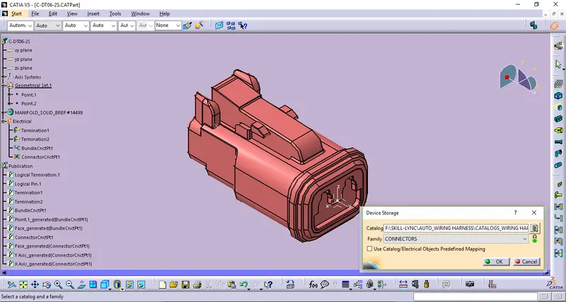
STEP_1: DEFINE AS ELECTICAL PART & ITS ELECTRICAL PROPERTIES
Initially shall we get all the given Connectors 3D CAD data are Create/Download from the given link www.te.com. Then by using Electrical Part Design Workbench in CATIA v5 we can define thus the part become Electically defined as well as its electrical properties are also defined. By the following that thus the Mechanical part becomes converted/defined as Electical part.
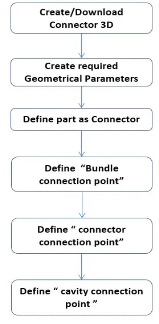
For Connectors it as to defined by following the below procedures and the definitions are,
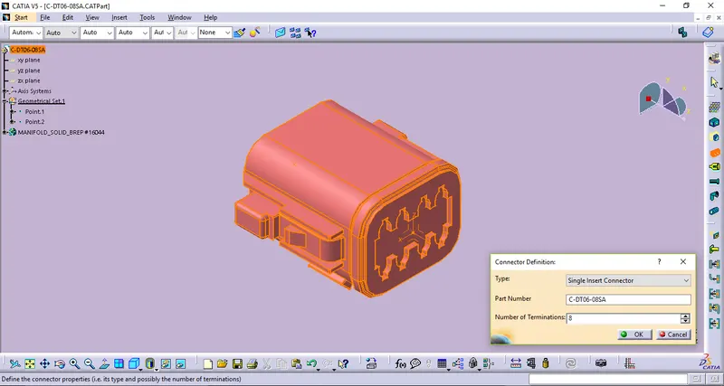
1_DT06-08SA
Defining connector
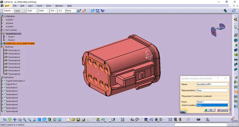
Defining Bundle Connection point definition.
Defining Connector Connection definition.
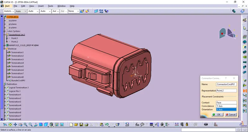
Then store data by using Store device definition to the apropriate catalog like Connector catalog.
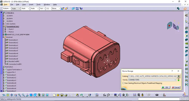
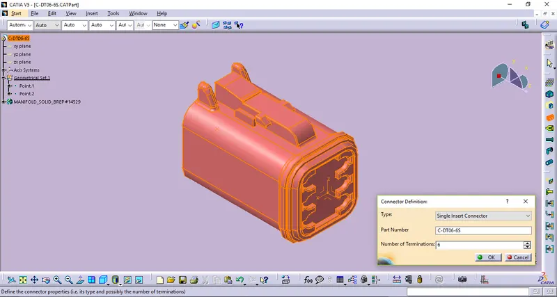
2_DT06-6S
Defining connector.
Defining Bundle Connection point definition.
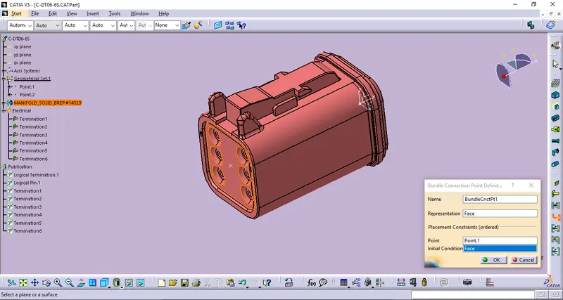
Defining Connector Connection definition.
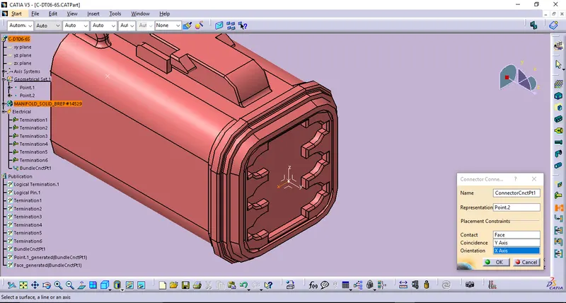
Then store data by using Store device definition to the apropriate catalog like Connector catalog.

3_DT06-4S
Defining connector.
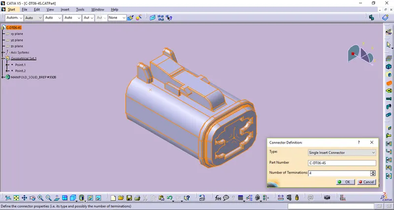
Defining Bundle Connection point definition.
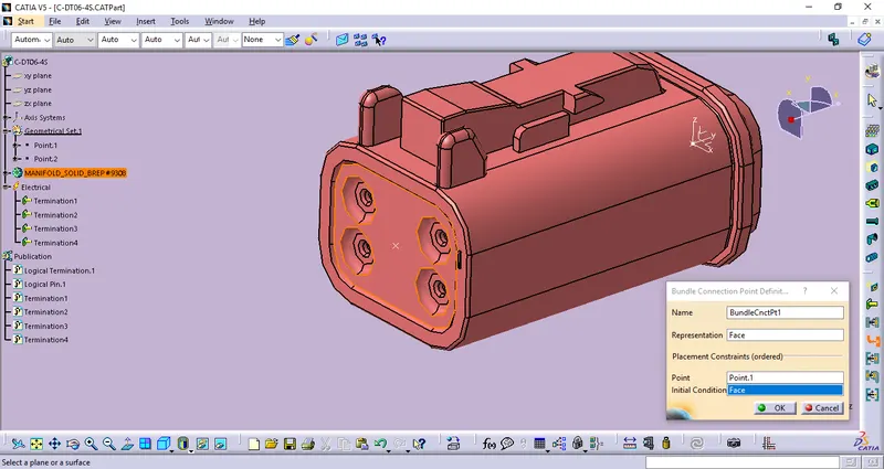
Defining Connector Connection definition.
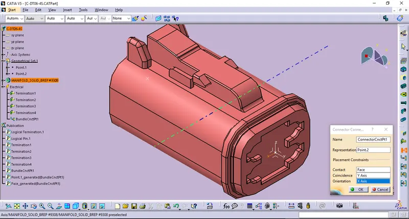
Then store data by using Store device definition to the apropriate catalog like Connector catalog.
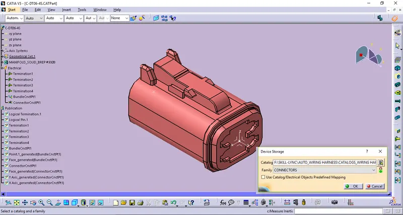
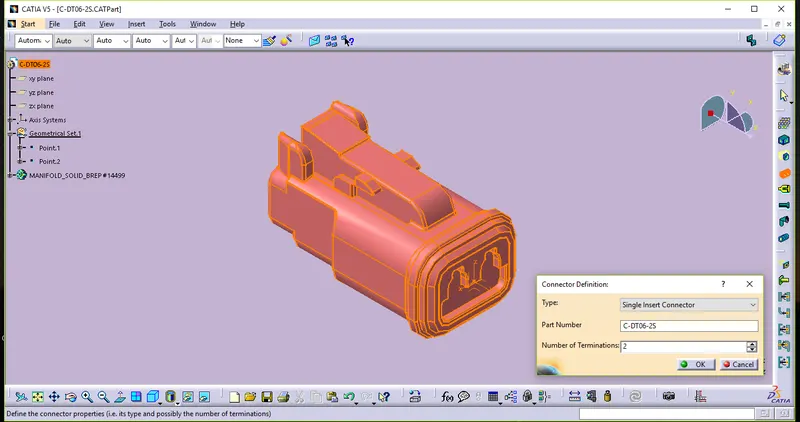
4_DT06-2S
Defining connector.
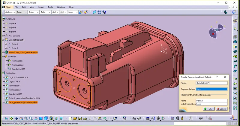
Defining Bundle Connection point definition.
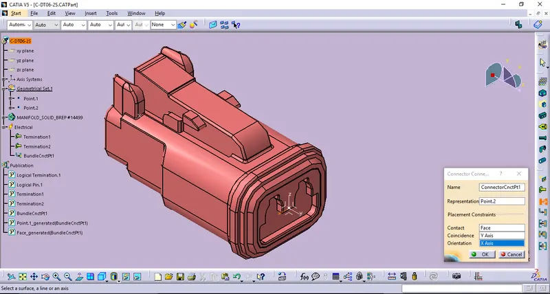
Defining Connector Connection definition.
Then store data by using Store device definition to the apropriate catalog like Connector catalog.
STEP_2:WIRING HARNESS ASSEMBLY WORKBENCH
- Once we were done all the electrical components definition then prepare to the Harness Assembly product. It consist as following as,
1. Harness Context Assembly -Top level Product assembly Which Contains Harness Geometrical Bundle/Ass And Electrical Bundle in itself.
2. Geometrical Bundle - Sub level product assembly like electrical components i.e, Connectors,Clips,Supports & etc.,
3. Electrical Bundle - Which contains as electrical circuit informations in itself.
2. Creating the main product Ass. then it has to be defined by using Geometrical Bundle in Harness Ass. it converted into Electical Harness Assembly Product.
3. Then insert all the defined electrical components in to Geometrical Bundle Ass.
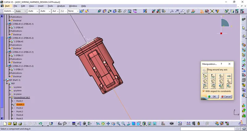
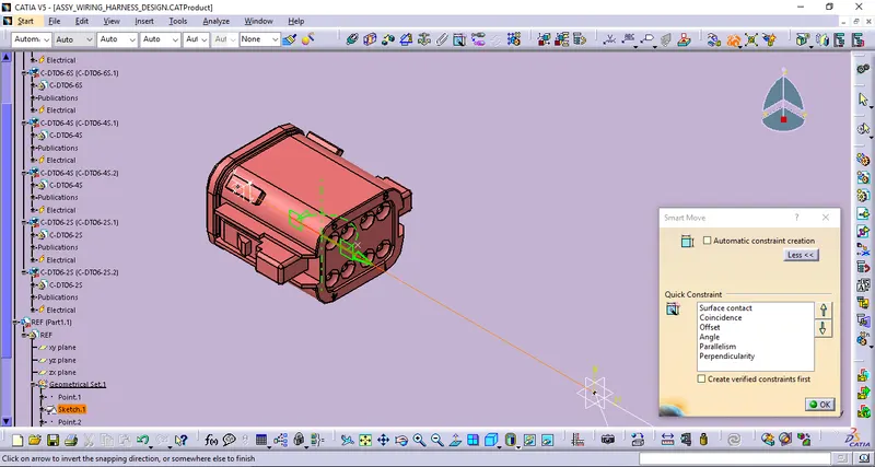
4. Then by using Move tool bar in Assembly workbench commands like Manipulation,Snap,Smart Move to arrange all the components in the appropriate locations by following the given routing layout.
REF'S,
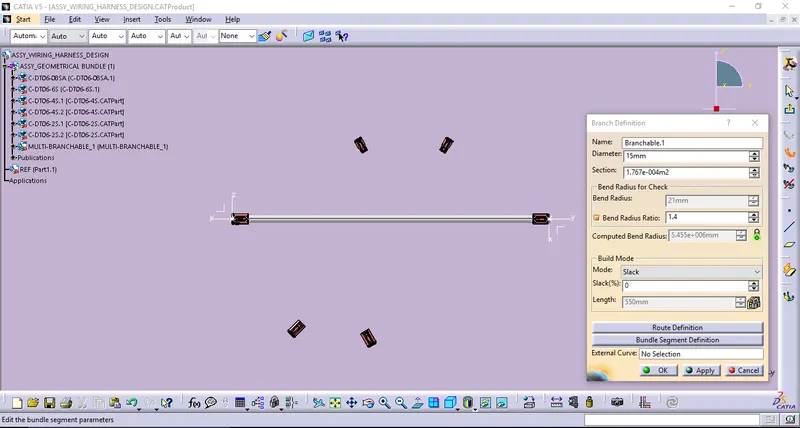
5. Then creating the wiring bundle segments in to the Multibrancable. In before that one we ensure thaat all the components and the Geometrical bundle also.
BUNDLE SEGMENTS:
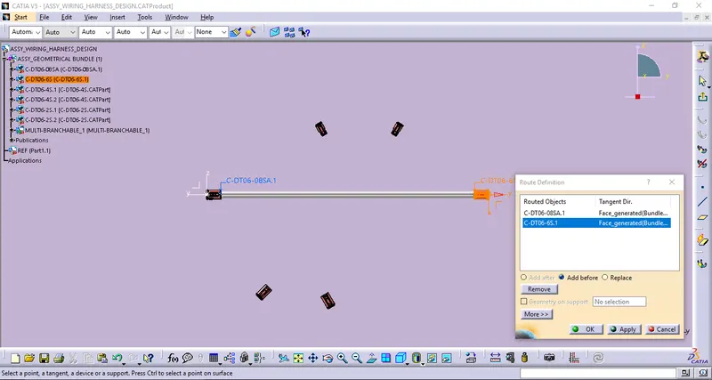
Defining Branch definition (Main Branch assumed Bundle dia 15 mm) & Routing definition,
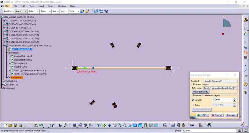
Defining Branch Point definitions,
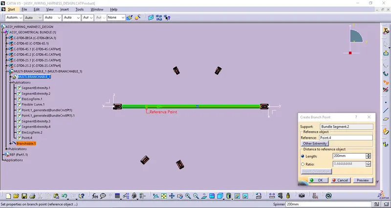
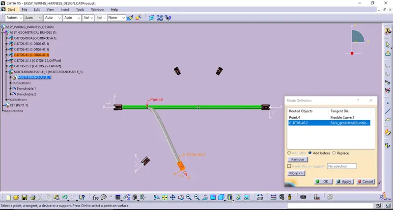
Defining Branch definition (Sub Branch assumed Bundle dia 10 mm) & Routing definition,
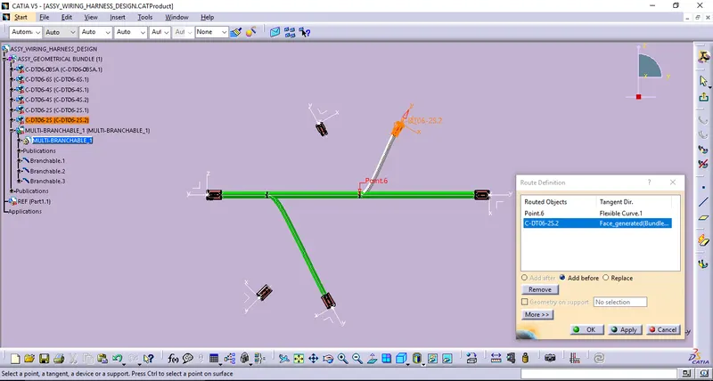
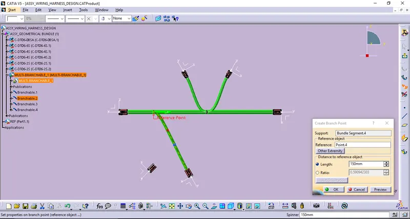
Defining Branch definition (Main Branch assumed Bundle dia 5 mm) & Routing definition,
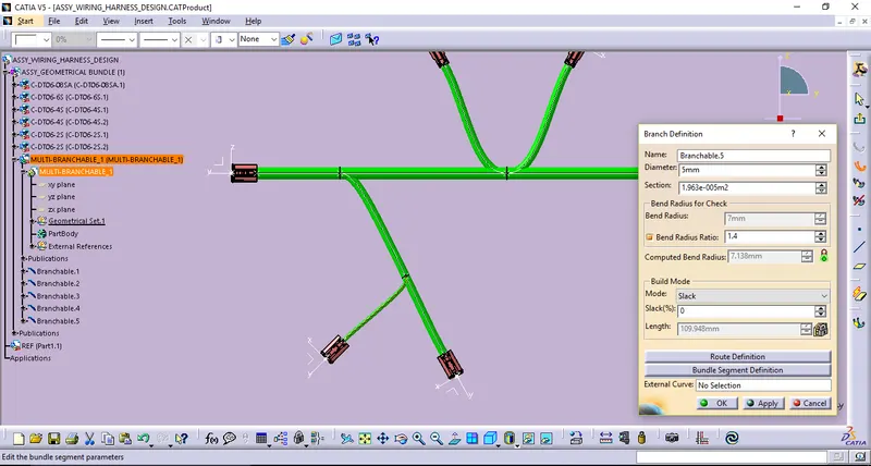
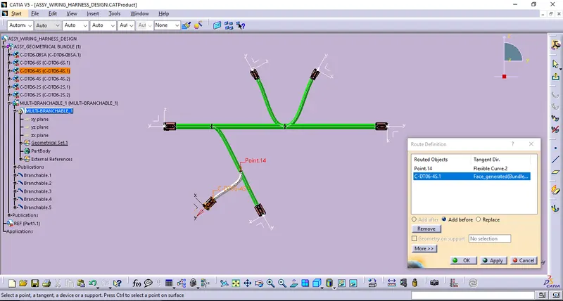
Defining Protective covering,
Appling COT_20mm for Main branch with the end extrimities(30mm).
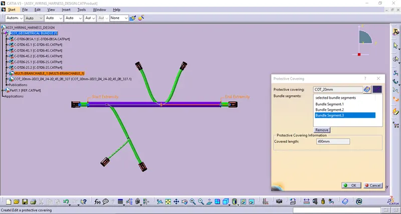
Defining end extrimities from the connectors end keep 30mm.
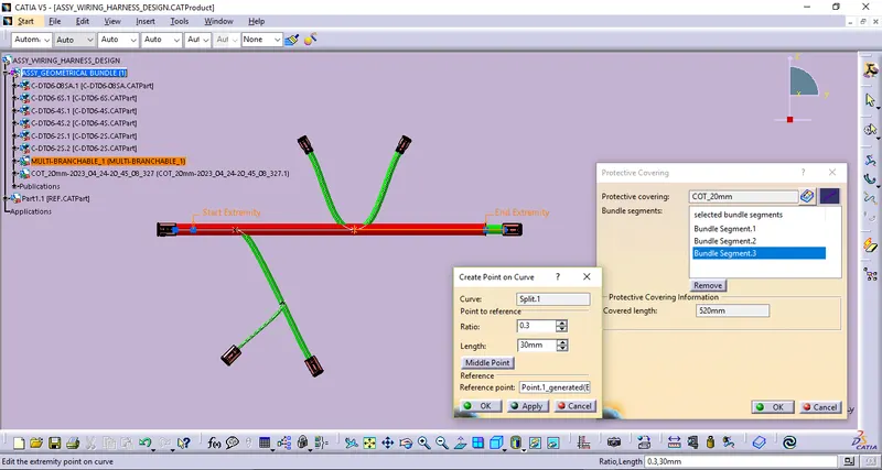
Appling COT_20mm for sub branches with the end extrimities(30mm).
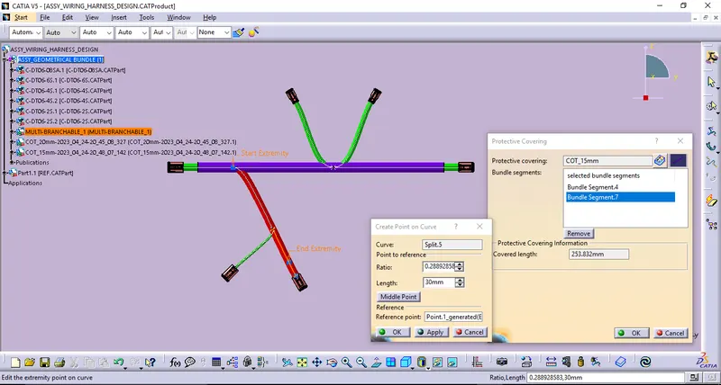
Defining Protective covering COT_10mm with end extrimities from the connector end keep 30mm.
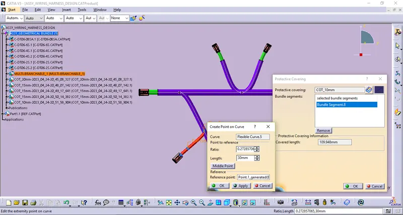
Final Harness Assembly 3D model.
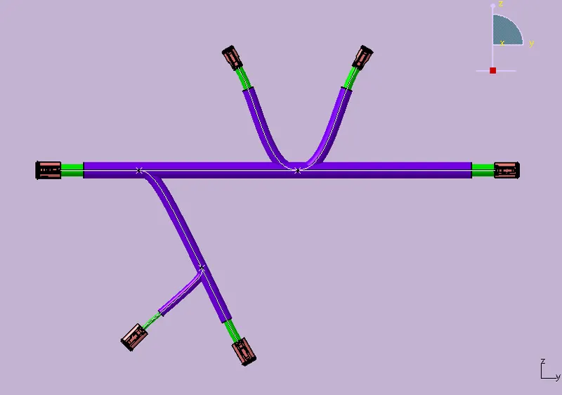
CONCLUSION:
Thus the given Wiring Harness Assembly Routing 3D model has to be completed by Using CATIA v5.