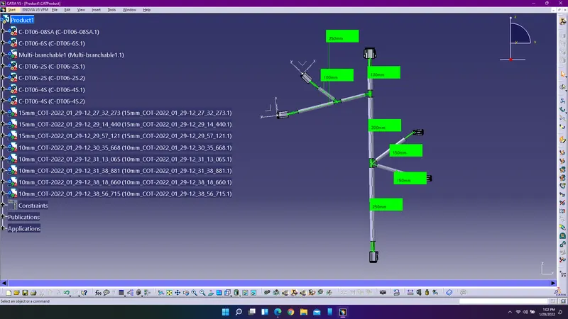
Wiring harness design in CATIA V5 - 3D modeling Week 4 Challenge
Aim: The aim of the challenge is to define the electrical parameters for the given component and adding them to the connectors catalogue and also provide routing for the connectors as per the challenge.
Procedure for defining electrical parameters for the given connectors:
1. Enter catia V5 and use part design workbench to create points on the connectors where ever there is requirement for connector and bundle connection. Insert an axis by selecting the point as orgin and make sure to allign the axis accordingly.
2. Enter into electrical part design workbench to define the electrical parameters for the given connectors.
3. Use define connector connection point and define bundle connection point to define the parameters for the given connectors.
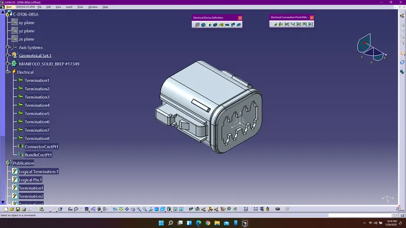
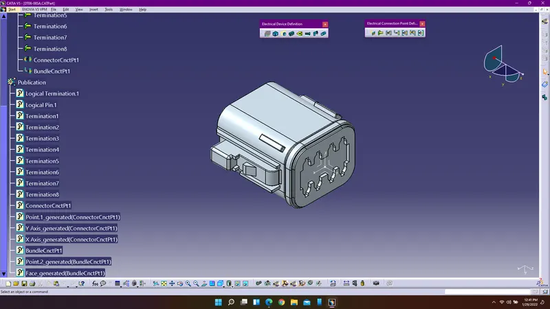
DT06-08SA
4. Similarly repeat the above steps to define the electrical parameters for other connectors.
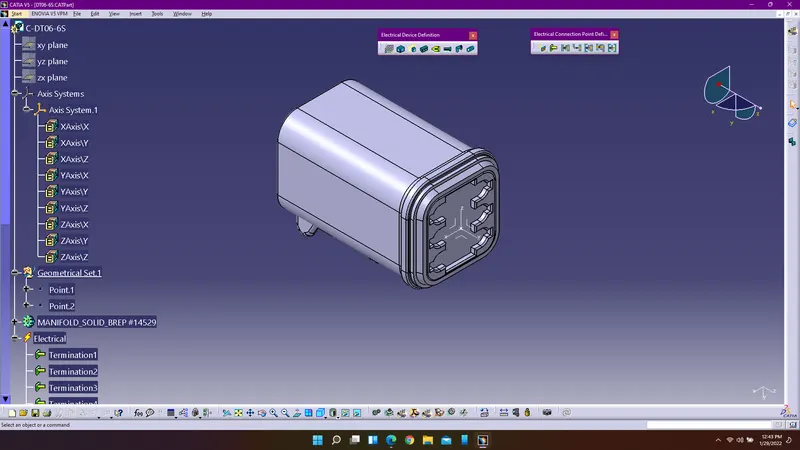
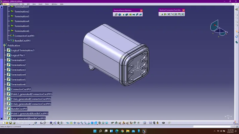
DT06-6S
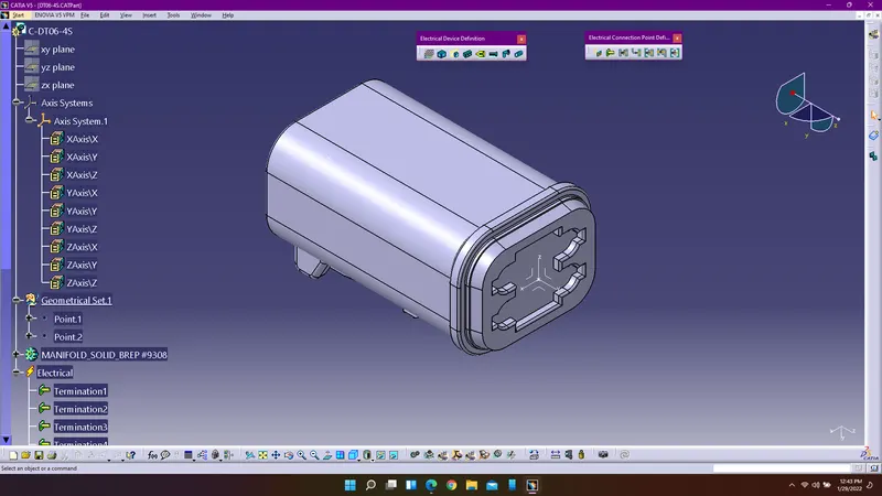
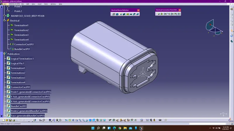
DT06-4S
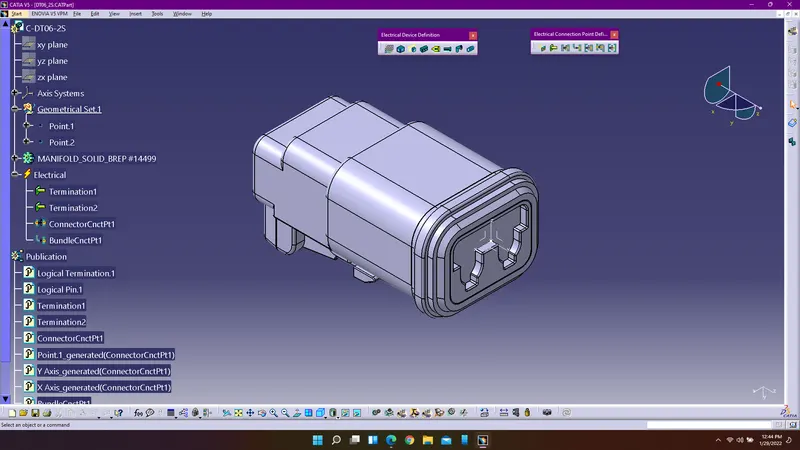
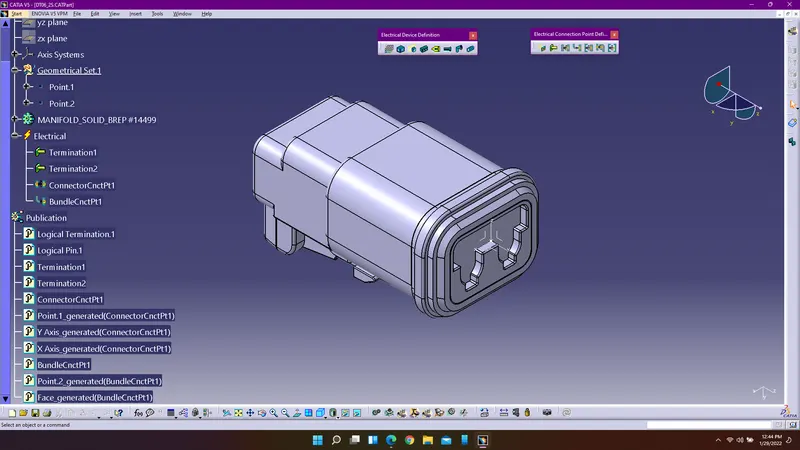
DT06-2S
Procedure for routing:
1. Enter into assembly design workbench and import all the electrically defined connectors into the assembly workbench.
2. Use Snap, smart move and manipulate commands to arrange the connectors according to the given challenge.
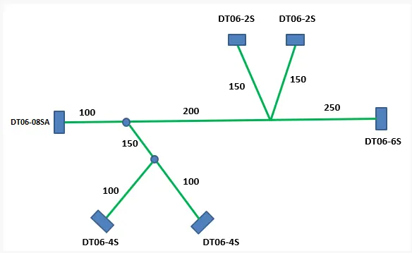
3. Enter into electrical harness assembly workbench and use the command geometric bundle to define the assembled product electrically.
4. Use multi branchable document to create the routing according to the given challenge and use add branch point command to create branch points accordingly.
5. Use corrugated tudes i.e.,. protective coverings for the electrical bundles using the catalogue browser.
6. Provide the protective coverings and use end extremity for the connectors end as 30mm length and measure the each branchable distances and keep the measure.