Wiring harness design in CATIA V5 - 3D modeling Week 4 Challenge
Aim
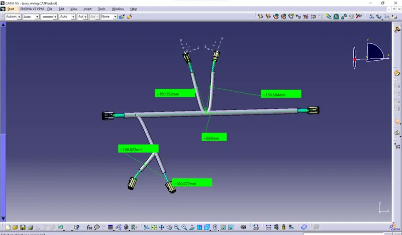
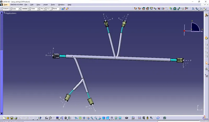
To create the electrical wiring harness routing for the montioned connectors and also give the protection for the wiring bundles.
Geometrical bundle
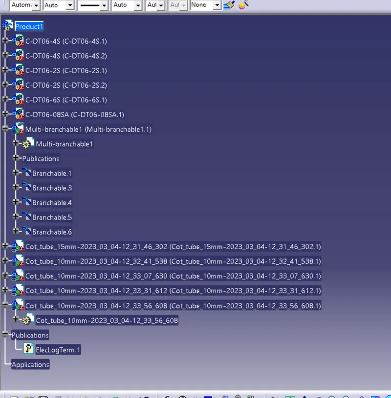
This is the sub level product file is the wire harness product that contains all of harness component i.e clips,supports,connectors,splies,grommets,annotation and actual physical bundel segment and branches.
Preaparation of harness assembly
- Creating the wirng harness geometrical bundle
- Inserting harness components into geometric bundle
- Position your inserted electric parts
- Connecting and disconnecting the electrical components
- Defining the wiring harness routing
( Ensure that all harness components that are needed is assembly are electrically defined with all required parameters before adding them in assembly , this is pre-requisite)
Creation of wiring harness bundle segments
- Switch to electrical harness assembly work bench
- Ensure that you have your harness bundle segements is geometrical bundle is highlighted.
- Select the create multi-branchable document icon.
- In the branch definition box input all the required parameters.
- Ensure that the bend radius ratio is set to 1.4 or greater than 1.5 and that the check box is on .
- Ensure the built mode set is ok.
Pre-requisites
- Geometrical bundle assembly is completed.
- All components are placed ay desired location .
- All type of electeical connectors /constrains are defined.
- Background geometry data is available & assembled in geometrical bundle context assembly
- All clips and clamps/ channles are placed at desired location
Positioning of electrical parts
There are some comments are used fro positioning the parts ,
They are,
Manipulation
This funcytion allows you to move rotate a component by free hand . This standard feature of mechanical assembly workbench.
Translation or rotation
This function allows you to move or rotate a component by a set value. This is standard feature of mechanical assembly workbench.
Snap
This function allows you to align a component by snapping from surface edge or point to the surface ,edge or point to another component. This is standard feature of mechanical assemble workbench.
Smart move
This function allows you to move your component by selecting a point,plane,face, surface from your component in a preview box then selecting a point ,line, face surface of the component you wish to move to
Conclusion
All the connectors are positioned at required position and the wiring harness routings are created and protection also provided to the bundle.