Fender Design Challenge
FENDER DESIGN
AIM
To create mount area for sill,drip,bumper,baffle(splash) abd drip area for the fender as per the given master diagram.
DEFINITION
Fender is a part of car,truc,motor cycles and other vehicles that frames or covers a wheel as well. It main purpose is to prevent debris,rocks,mud,liquids,sand and other road debriss getting from the wheel during the roatation. 'The fender' typically refers to the front panel that covers the front wheel, and the ' quarter panel' typically refers to the rear panel that covers the wheel aslo includes the roof pillar.
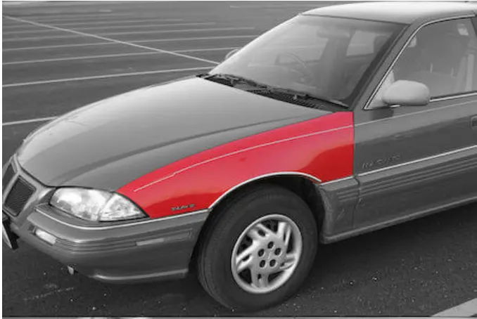
FIG:- FRONT FENDER
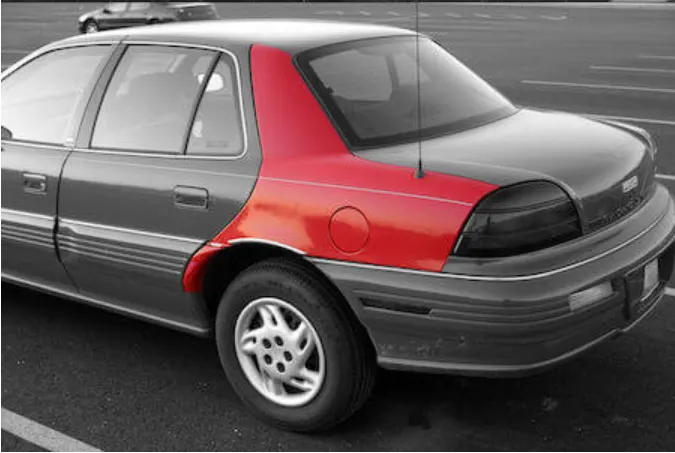
FIG:- REAR FENDER
FUNCTION OF FENDERS
- Its avoid the other vehicles or pedestrian on the road side dirty.
- Its controls the pedestrian hurting.
- Its controls the scratch the body of other vehicles.
- Its minimize the minor and even major damage to other vehicles.
- Its used to covers the engine compartment.
Types of fender
Fender have two types . They are,
1)Full fender type
2)Half fender type
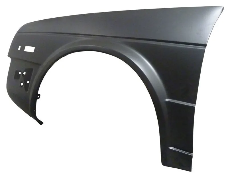
FIG:- FULL FENDER TYPE
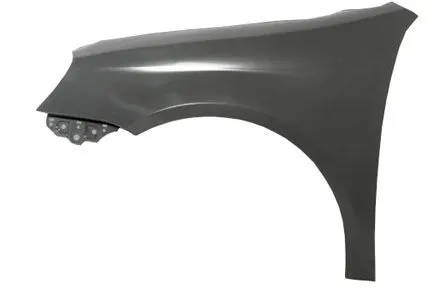
FIG:- HALF FENDER TYPE
MOUNTING POINTS OF FENDER
- Drip area mounting
- Bumper mounting
- Baffle mounting
- A pillar mounting
- Sill mounting
- Cowl mounting
DRIP AREA MOUNTING
- Its the major and important mounting of the fender.
- Its mounted with the engine compartment.
- Drip area is positioned around 200mm from the rear end of the fender and 150mm from the front end of the fender.
- From the fender skin its have the 3degree inclanation for to hide the inner view of the engine.
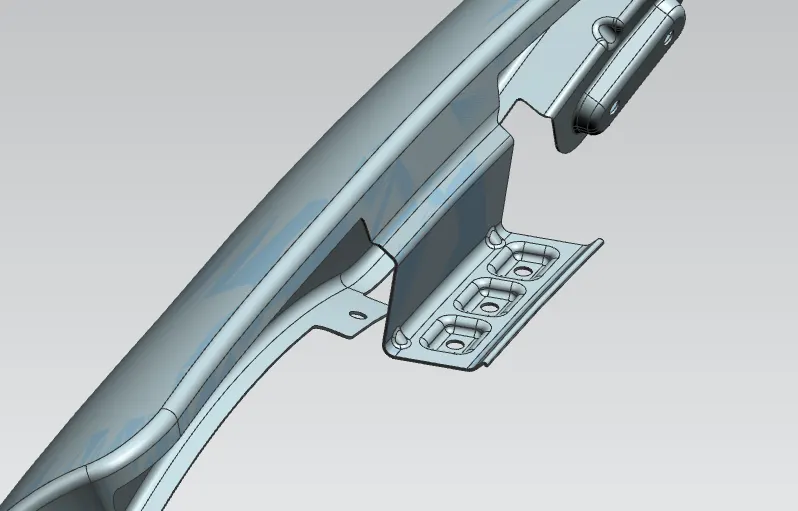
FIG:- DRIP AREA MOUNTING
BUMPER MOUNTING
- This mounting is provided for the bumper installation in the car.
- Bumper is used to absorbs the external forces from the outside of the car during the hitting of other vehicles.
- Its also gives the safety to the pedestrian.
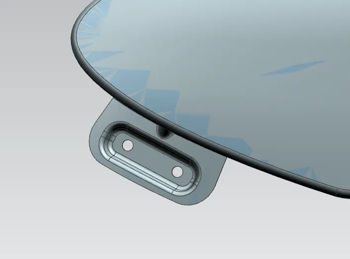
FIG:- BUMPER MOUNTING
BAFFLE MOUNTING
- Baffle is the one form of rubber or elastic material , its used to absorb the vibration inside the car.
- Its used tonreduce the noise from the engine compartment.
- Its mounted on the wheel arc area with 3 mounting pints on the fender.
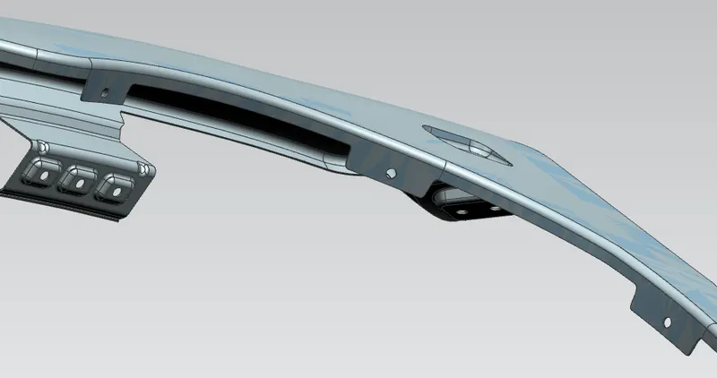
FIG:- BAFFLE MOUNTING
SILL MOUNTING
- Its the joining point of the fender to the lower portion the vehicle body.
- Its gives the stability at the lower portion of the fender.
-
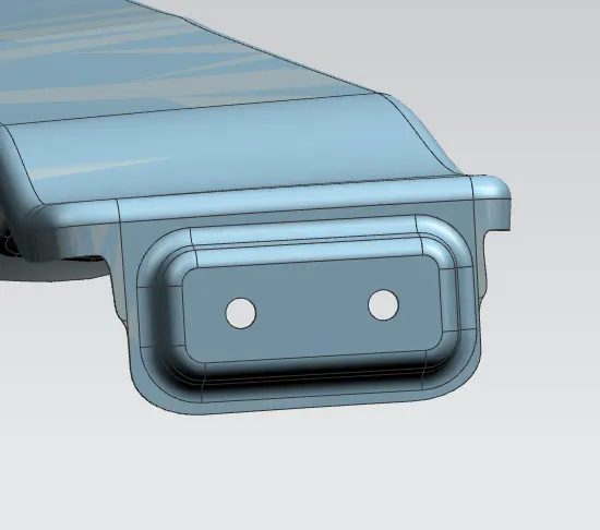
FIG :- SILL MOUNTING
A PILLAR MOUNTING
- Its the upper joining point of the fender.
- In thid portion the fender is connected with the vehicle body with particular angle.
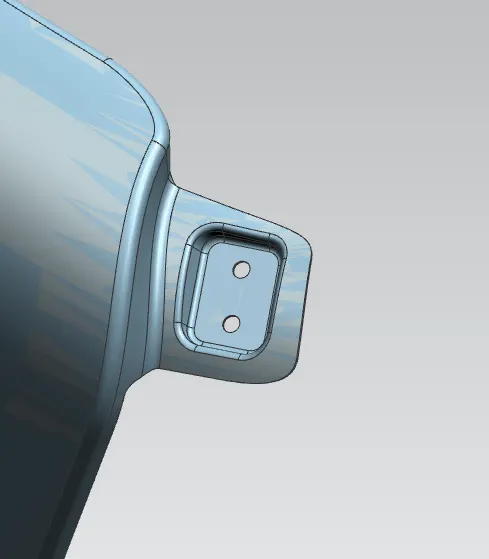
FIG:- A PILLAR MOUNTING
MOUNTING FOR TURN SIGNAL LIGHT
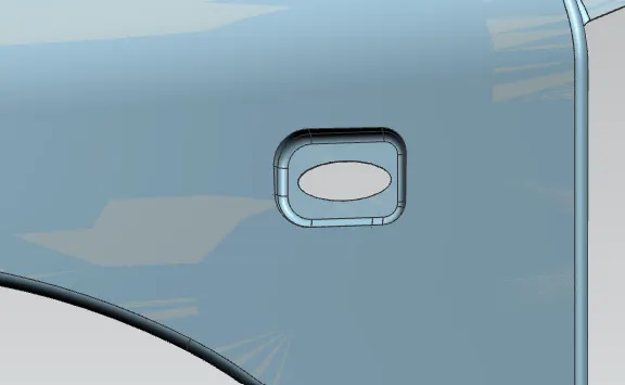
FIG:- TURN SIGNAL LIGHT MOUNTING
MANUFACTURING PROCESS OF FENDER
Fender and other car parts are manufactured by the injection molding process.
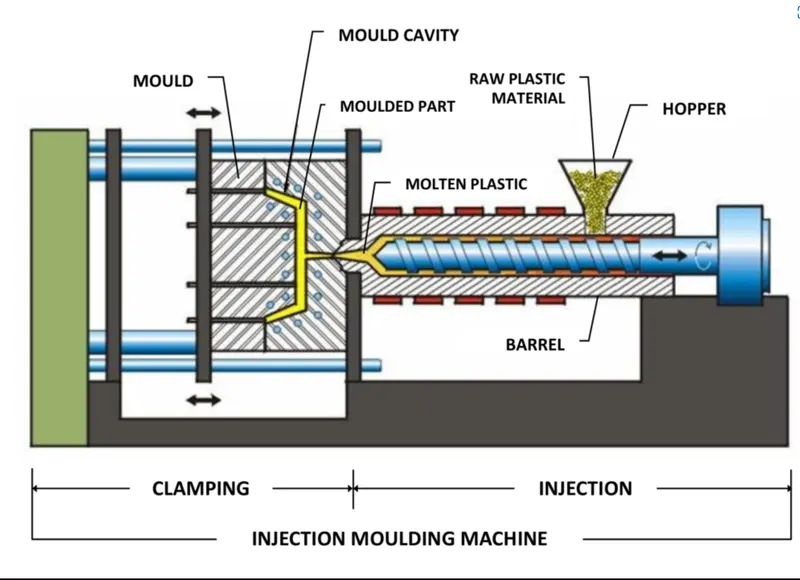
FIG:- INJECTION MOLDING
Injection molding has 4 stages . they are,
Filling stage
Cooling stage
Packing stage
Releasing stage
1) FILLING STAGE
Filling the molt cavities is the first step in this process, the mold cavities would be filled about 95% in this stage. Generally the shorter filling time gives the higher molding efficiency, but in the practice , the injection molding time or speed is influenced by many other factors.
the viscocity of the material flow
injection pressure
setting the injection speed
runner and friction loss
mold structure
mold temperature setting
2) PACKING STAGE
The holding pressure is continously applied in packing stage, the melt compacted to increase the density of the plastic to componsate for plastic shrinkage behavior, in packing process the pressure in the cavity is high because its almost filled. injection molding machine screw are still moving forward slightly, plastic flow rate become very slow, in the packing stage,plastic mold wall is cooled down and solidified until the gate is closed.
Holding pressure and speed is usually 50% to65% of the maximum pressure and speed of filling, which means holding pressure is 0.6-0.8 MPa lower than the injection pressure.
3) COOLING STAGE
The design og cooling system in injection molding is very important. Because the molded plastic article to need to be cooled and solidified to avoid the deformation and damage. The cooling time of the takes 70% to 80% of injection molding cycle, so a well designed cooling system can shorten the molding time and improve the productivity magnificently. Poor designed coolinf system will improve the cooling time ; increase cost . Uneven cooling can make the damage and deformation of the plastics.
4) RELEASING STAGE
The last process of the injection molding process is releasing the parts from the mold cavities, its also called as demolding.Even the plastic parts can be cooled down and solidified during cooling stage, but we still need to careful for the way of releasing. Unproper way will deform the plastic molded parts or even cause damage.There are two common methods os releasing , injector and stripper plate, which way to go depends on the mold plastic structure.Ejector layout should be uniform to achieve stable releasing.
PARAMETERS USED IN FENDER DESIGN
1) CURVE ON SURFACE
Its use to create the curve on the surface
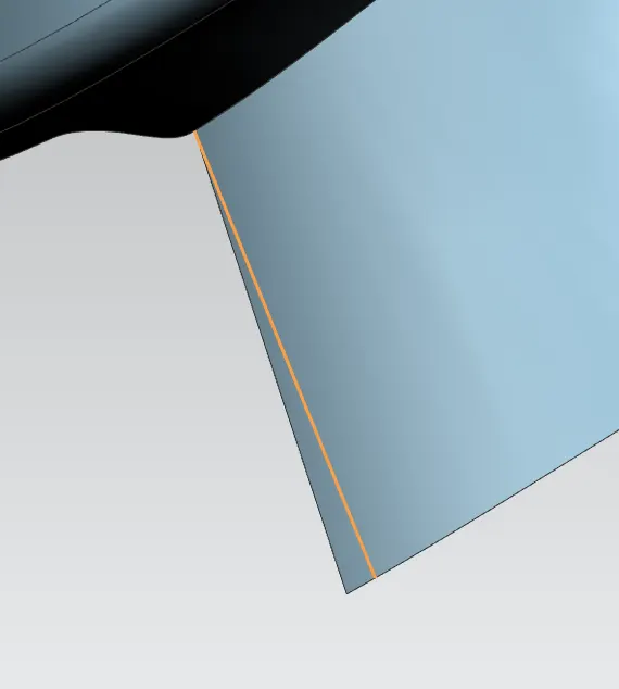
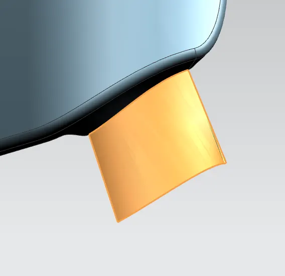
2) LAW EXTENSION
Its used to extend the sheet with respect to the required and required length
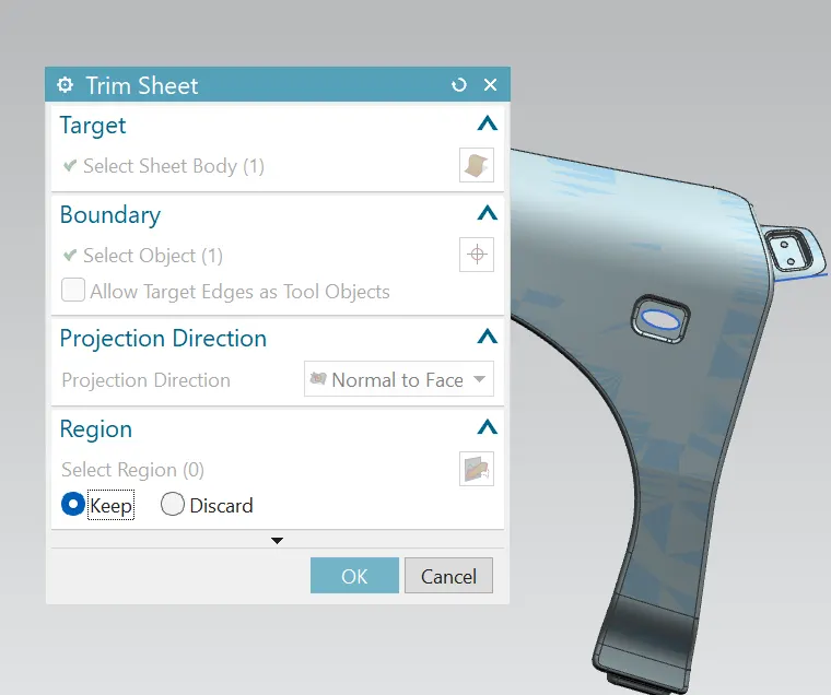
3) TRIM SHEET
Its used to remove the unwanted portion or area froom the surface of the body
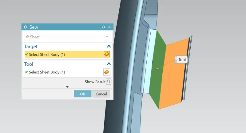
4) SEW
Its used to sewing the two or more single faces to the one unique face
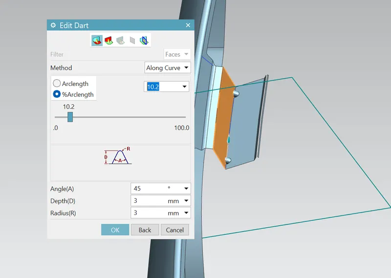
5) DART
Its used to create the darts inbetween the edges . The darts are provieds the addditional strength to the faces and minimizing the vibration of the faces.
CONCLUSION
The mount area for sill,bumper,A pillar,baffle( splash) and drip area is successfully created as per the given master diagram. And the manufacturing of fender and design parameters are explained.