Wiring harness design in CATIA V5 - 3D modeling Week 4 Challenge
OBJECTIVE:
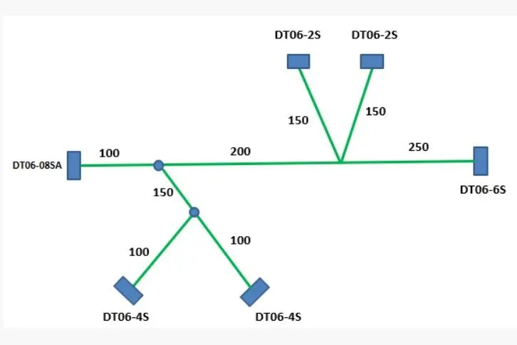
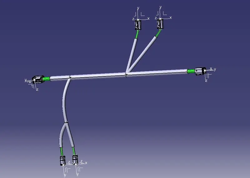
- To Route the following harness layout in the Electrical workbench.
- Add protective covering on all branches.
REQUIREMENTS:
- CATIA V5.
- Knowlege of using CATIA V5.
GIVEN
CAD data of the following Connectors:
- DT06-4S.
- DT06-6S.
- DT06-2S.
- DT06-08SA.
LAYOUT DIAGRAM
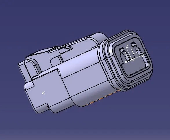
DT06-2S.
PROCEDURE
The following was defined for all the connectors:
- Connector connection point.
- bundle connection point.
- axis system at the connector connection point.
- define all the connectors as electrical components.
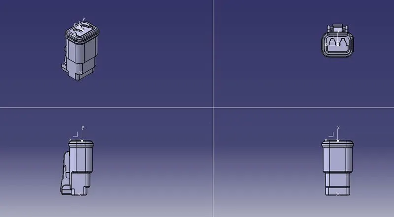
ORIENTATION VIEWS
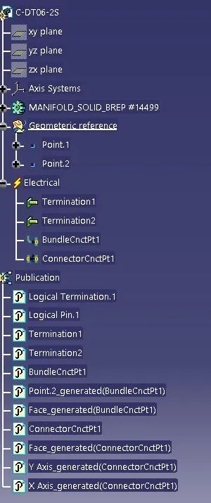
FEATURE TREE
DT06-4S.
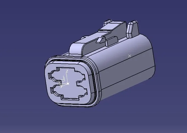
PROCEDURE
The following was defined for all the connectors:
- Connector connection point.
- bundle connection point.
- axis system at the connector connection point.
- define all the connectors as electrical components.
ORIENTATION VIEWS
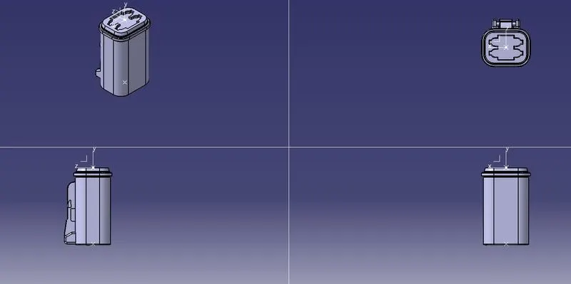
FEATURE TREE
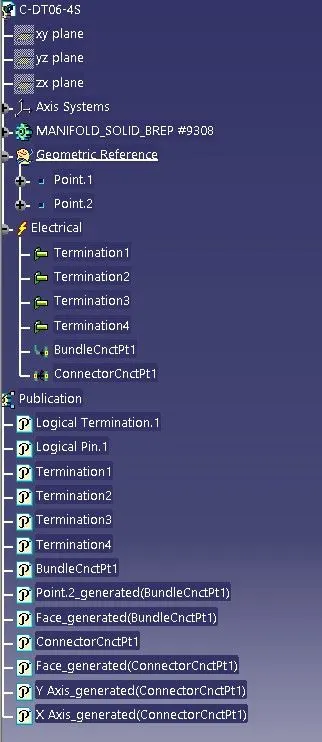
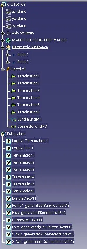
DT06-6S
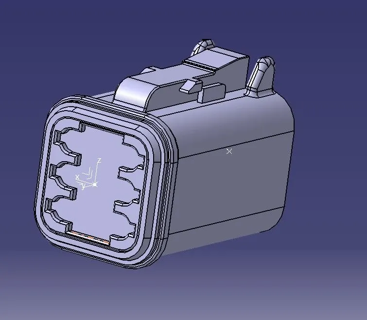
PROCEDURE
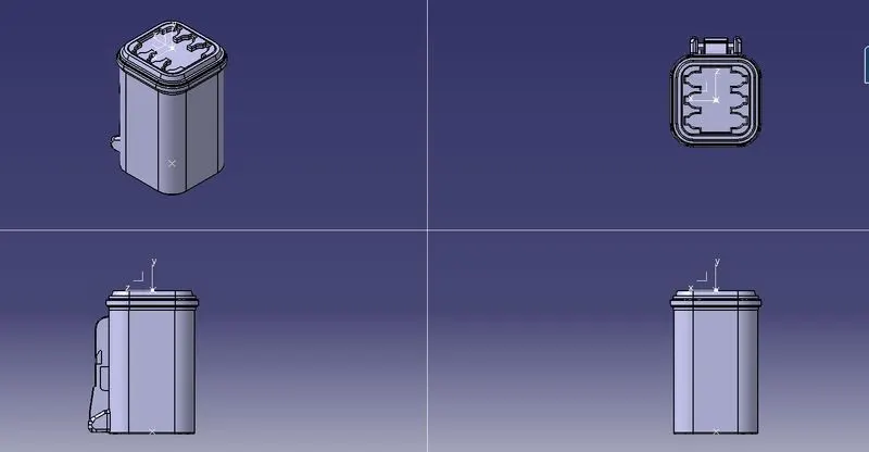
The following was defined for all the connectors:
- Connector connection point.
- bundle connection point.
- axis system at the connector connection point.
- define all the connectors as electrical components.
ORIENTATION VIEWS
FEATURE TREE
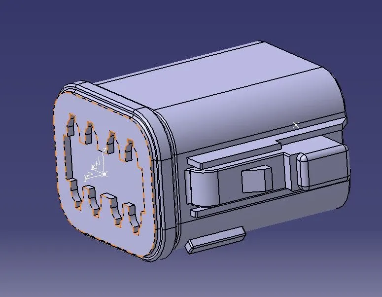
DT06-08SA
PROCEDURE
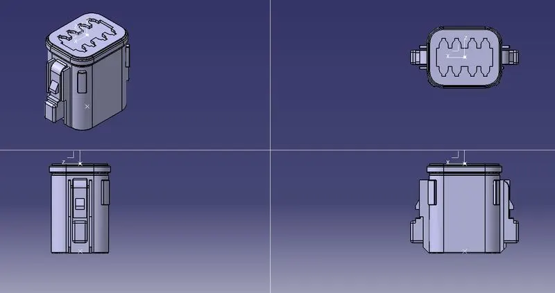
The following was defined for all the connectors:
- Connector connection point.
- bundle connection point.
- axis system at the connector connection point.
- define all the connectors as electrical components.
ORIENTATION VIEWS
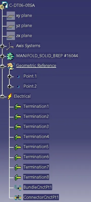
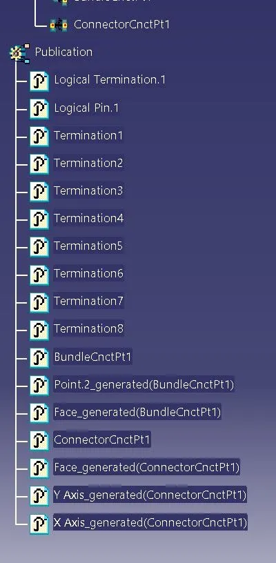
FEATURE TREE
ASSEMBLY PART
PROCEDURE
- Create Product File and rename.
- Import all the Connector files into it.
- open assembly under mechanical bench.
- Move according to its required position.
- open the file in harness assembly bench.
- create the wire connections between them with proper diameter and carefully choosing the positions and directions.
- exit the harness workbench where it leads to electrical assembly bench.
- use created cot tube to apply on them.
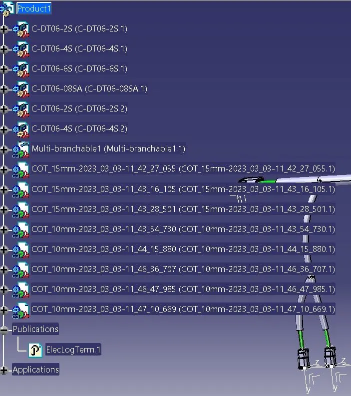
FEATURE TREE
CONCLUSION
The Connections between connectors were properly given using CATIA V5 and experimented carefully.