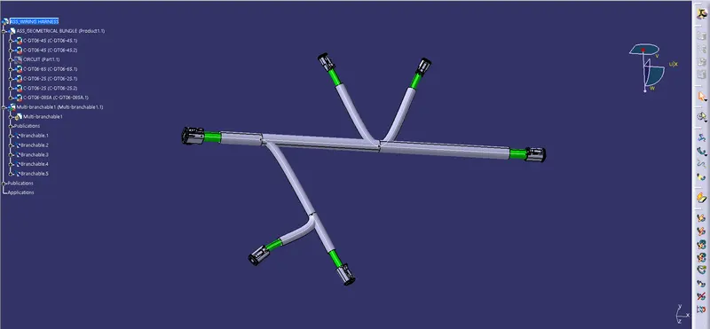
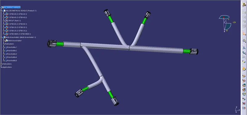
Wiring harness design in CATIA V5 - 3D modeling
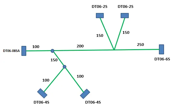
AIM:- Route the following harness layout in the Electrical workbench. Make assumptions for harness bundle diameters. Use the following connectors as shown in the layout diagram.
Add protective covering on all branches connected to DT06-2S & DT06-4S connectors. Keep end extremity at 30mm (from connectors end)
Download connector 3D data from www.te.com
- DT06-4S
- DT06-6S
- DT06-2S
- DT06-08SA
1. Defining Deutsch DT06 – 08SA:
- The connector is downloaded from the given link
In Part Design Work Bench:
- The Connector Connection Point and the Bundle Entry Point are defined on their respective mating faces
- The required axis system is defined for the connector connection point
- Then the Work Bench is changed to 'Electrical Part Design'
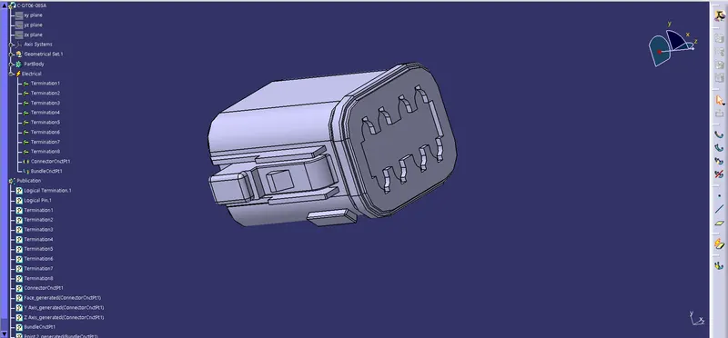
In Electrical Part Design Work Bench:
- The connector is defined as a connector with
- Type: Single Insert Connector
- Part Number: C-DT06-08SA
- Number of Terminations: 8
- Then the connector connection point is defined with
- Representation: Connector_Connection_Point
- Contact: Mating Face
- Coincidence: Y-Axis
- Orientation: X-Axis
- Then the Bundle Entry Point is defined with
- Representation: Mating Face
- Point: Bundle_Entry_Point
- Initial Condition: Mating Face
2. Defining Deutsch DT06 – 6S:
- The connector is downloaded from the given link
In Part Design Work Bench:
- The Connector Connection Point and the Bundle Entry Point are defined on their respective mating faces
- The required axis system is defined for the connector connection point
- Then the Work Bench is changed to 'Electrical Part Design'
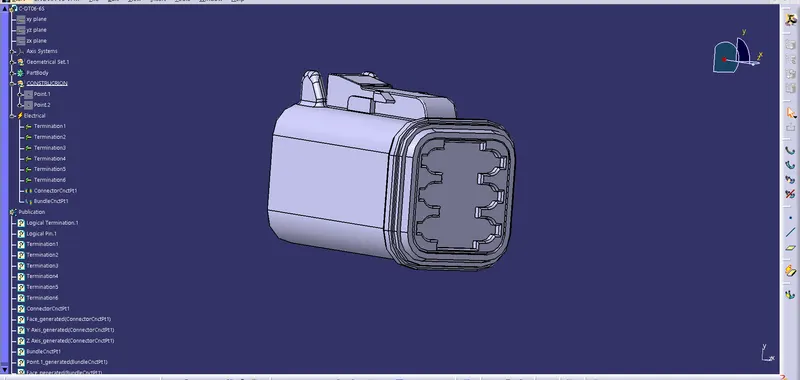
In Electrical Part Design Work Bench:
- The connector is defined as a connector with
- Type: Single Insert Connector
- Part Number: C-DT06-6S
- Number of Terminations: 6
- Then the connector connection point is defined with
- Representation: Connector_Connection_Point
- Contact: Mating Face
- Coincidence: Y-Axis
- Orientation: X-Axis
- Then the Bundle Entry Point is defined with
- Representation: Mating Face
- Point: Bundle_Entry_Point
- Initial Condition: Mating Face
3. Defining Deutsch DT06 – 4S:
- The connector is downloaded from the given link
In Part Design Work Bench:
- The Connector Connection Point and the Bundle Entry Point are defined on their respective mating faces
- The required axis system is defined for the connector connection point
- Then the Work Bench is changed to 'Electrical Part Design'
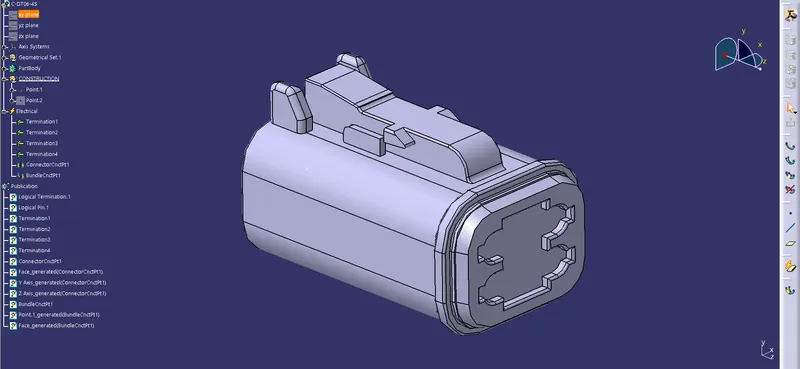
In Electrical Part Design Work Bench:
- The connector is defined as a connector with
- Type: Single Insert Connector
- Part Number: C-DT06-4S
- Number of Terminations: 4
- Then the connector connection point is defined with
- Representation: Connector_Connection_Point
- Contact: Mating Face
- Coincidence: Y-Axis
- Orientation: X-Axis
- Then the Bundle Entry Point is defined with
- Representation: Mating Face
- Point: Bundle_Entry_Point
- Initial Condition: Mating Face
4. Defining Deutsch DT06 – 2S:
- The connector is downloaded from the given link
In Part Design Work Bench:
- The Connector Connection Point and the Bundle Entry Point are defined on their respective mating faces
- The required axis system is defined for the connector connection point
- Then the Work Bench is changed to 'Electrical Part Design'
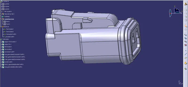
In Electrical Part Design Work Bench:
- The connector is defined as a connector with
- Type: Single Insert Connector
- Part Number: C-DT06-2S
- Number of Terminations: 2
- Then the connector connection point is defined with
- Representation: Connector_Connection_Point
- Contact: Mating Face
- Coincidence: Y-Axis
- Orientation: X-Axis
- Then the Bundle Entry Point is defined with
- Representation: Mating Face
- Point: Bundle_Entry_Point
- Initial Condition: Mating Face
Creating the required harness routing:
- A sketch create on a plane with dimensions appropriate for the dimensions of the entire harness assembly
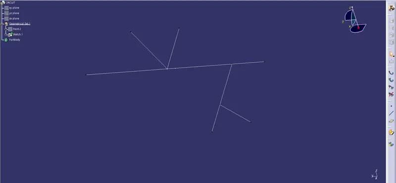
- A new product is created and named Assy_Wiring_Harness_Context
- Another new product under the Assy_Wiring_Harness_Context is created and named Assy_Geometric_Bundle
- All the connectors are imported into the Assy_Geometric_Bundle
- The positioning sketch is imported into Assy_Wiring_Harness_Bundle
- The connectors are moved and oriented on the sketch according to the requirements
- The Workbench is switched to 'Electric Harness Assembly
- A 10mm branch with a 1.4 bend radius ratio and 0% slack between connectors DT06-08SA and DT06-6S is created
- A branch point is created at a distance of 100mm from DT06-08SA
- A 2nd branch point is created at a distance of 200mm from the 1st branch point
- A 5mm branch with a 1.4 bend radius ratio and 0% slack from the 1st branch point on the main branch and DT06-4S connector is created
- A 3rd branch point is created at a distance of 150mm from the 1st branch point on the 5mm branch
- A 5mm branch with a 1.4 bend radius ratio and 0% slack between the 3rd branch point and another DT06-4S connector is created
- A 5mm branch with a 1.4 bend radius ratio and 0% slack from the 2nd branch point on the main branch and the DT06-2S connector is created
- A 5mm branch with a 1.4 bend radius ratio and 0% slack between the 2nd branch point on the main branch and another DT06-2S connector is created
- A 10mm corrugated tube protective covering is applied on the main branch with a 30mm end extremity from the connectors and a 5mm corrugated tube protective covering is applied on the sub-branches with a 30mm end extremity from the connectors by clicking on the 'Protective Covering' icon from the 'Electric Harness Assembly' workbench.