Radar Mast & Final Assembly of Yacht
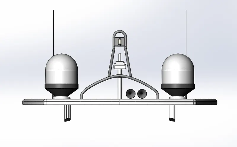
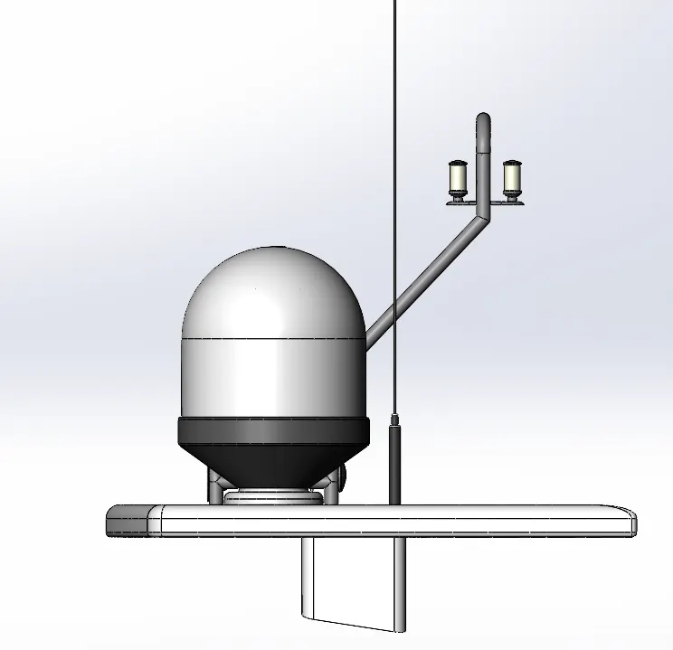
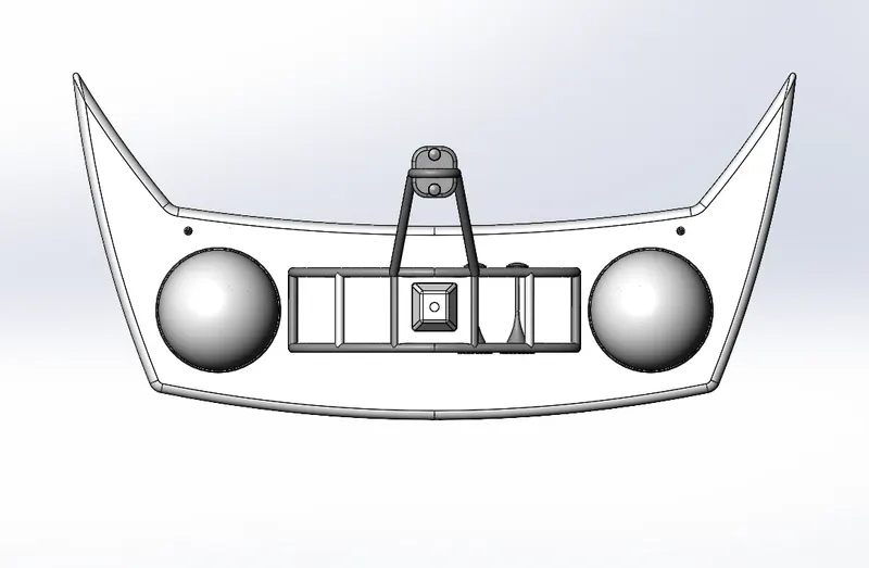
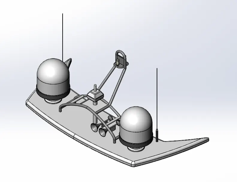
1. RADAR MAST
2. YACHT ASSEMBLY
 0
0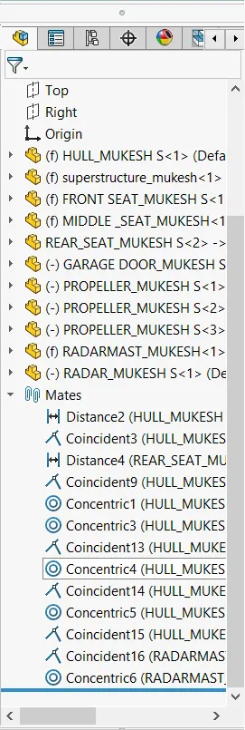
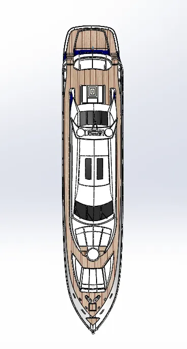
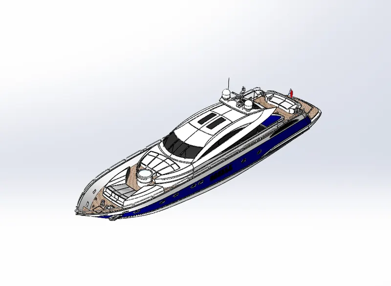
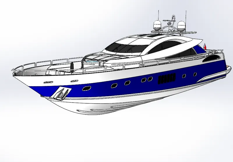
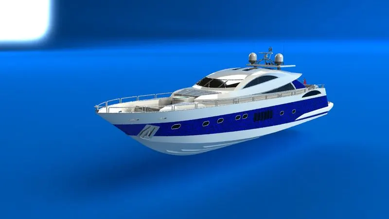
Modeling and Assembly of Sunseeker predator yatch
objective:
The main aim is to produce a detailed model of different parts of yatch with the help of blueprints and some given dimensions and to assemble the entire model using Solidworks
Introduction:
- The yacht assembly comprises part modeling as well as surface modeling.
- The surface modeling environment is used up to 90% in the yatch assembly
- most of the part bodies are modeled using blueprints only
- assembling and visualization play an essential role in any model that we create in a cad software
in the process of modeling a Sunseeker predator yatch, we design a part of a model using initial 2d sketches and then we turn them into 3d models using the tools like surface tools featuring tools, etc.
Design methodology/design approach:
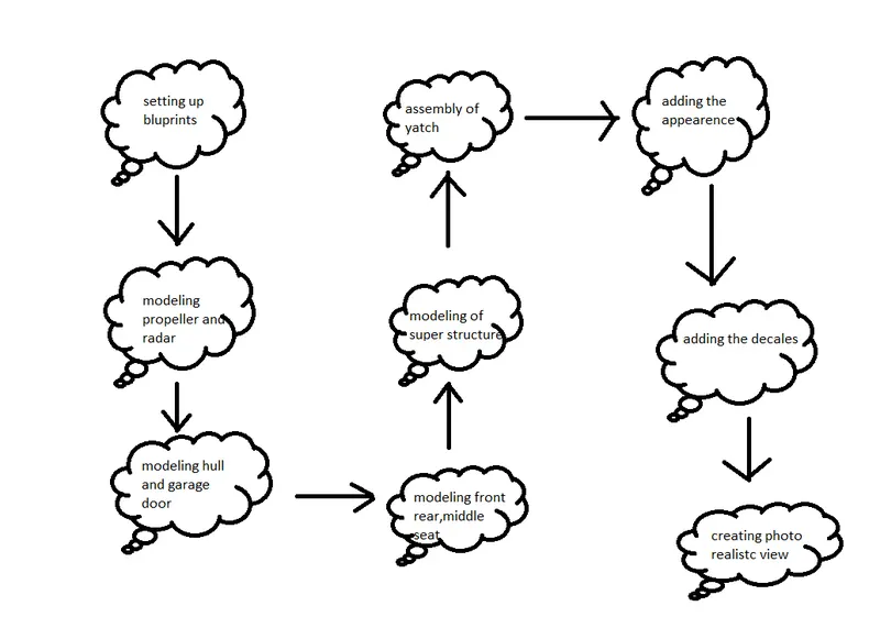
Part of being modeled:
- propeller
- radar
- hull
- garage door
- rear seat
- front seat
- middle seat
- superstructure
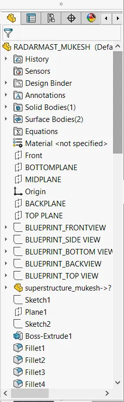
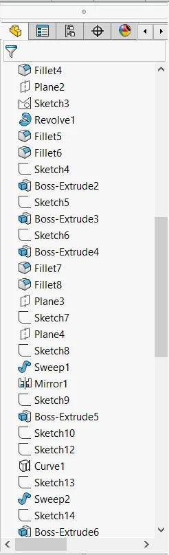
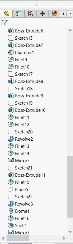
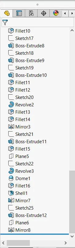
- radar mast
Type of commands
Sketch
Create the sketches and decide how to dimension and where to apply relations.
Features
Select the appropriate features such as extrude and fillets determine the best feature to apply and what order to apply those features must be decided
Surface
The surface is a type of geometry that can be used to create solid features
Assembly
By using the mates the created parts will be assembled
Feature commands
Extrude boss /base - it will allow us to take a 2d sketch and add thickness to it in the third dimension.
Extruded cut-Extruded cut feature removes material from the part. The End Condition, Draft, and Thin Feature options are the same as described in Extruded Boss/Base. To create an extruded cut: 1) Sketch the profile for a cut. 2) Click Extruded Cut on the Features toolbar or select Insert, Cut, Extrude on the menu bar.
Split -The Split Line tool projects an entity (sketch, solid, surface, face, plane, or surface spline) to surfaces, or curved or planar faces. It divides a selected face into multiple separate faces. You can split curves on multiple bodies with one command.
Dome- It can add one or more domes to the selected planar or non-planar faces. the software calculates the distance using the radius of the arc as a basis for the dome.
Pierce relationship -A pierce relationship is required to ensure that two entities from different axis collide or cross paths – the center point of entities can be selected to move the sketch entity to a mutual position. To apply a pierce relation a line and a sketch point are required.
Composite curve -Composite curves are T/H diagrams (temperature/heat diagrams) used to visualize cold and hot streams and potential heat transfer between them. It is a graphical technique used for visualizing the heat cascade. combining curves, sketch geometry, and model edges into a single curve. Use a composite curve as a guide curve when creating a loft or a sweep. To create a composite curve: Click Composite Curve on the Curves toolbar, or click Insert, Curve, Composite.
Surface modeling:
Surface modeling is an alternative to solid body modeling. Essentially, it's just another tab at the top of the SOLIDWORKS User Interface. Surface modeling is an important tool to have in your box because it not only makes modeling easier, it sometimes makes modeling possible.
surface commands:
lofted surfaces  -A loft feature is an important tool for (surface) modeling in SolidWorks. The loft feature creates a shape by making transitions between multiple profiles and guide curves. This tool is very valuable for modeling complex surfaces. You can do some really cool stuff when you use this feature properly.
Extrude surface-extrudes a sketch are selected sketch contours in one or two directions to create a surface features.
Revolved surfaces-Choose different sketches from intersecting or non-intersecting sketches to create the revolve with the Selected Contours pointer. To create a revolved surface: Sketch a profile and a centerline around which to revolve the profile. Click Revolved Surface (Surfaces toolbar) or Insert > Surface > Revolve.
Sweep Surfaces-To create a swept surface: Create planes for sketching the sweep profile, sweep path, and if necessary, the guide curves. Sketch the sweep profile and path on the planes that you created. You can also sketch the sweep path on a model face or use a model edge for the path.
Filled surface-The Filled Surface feature constructs a surface patch with any number of sides, within a boundary defined by existing model edges, sketches, or curves, including composite curves. You can use this feature to construct a surface to fill a gap in a model.
Ruled surface-The Ruled Surface command creates surfaces that extend out in a specified direction from selected edges. Examples of how you can use ruled surfaces: Add tangent extensions to complex surfaces. Create drafted sidewalls.
Trim surface - Trim Surface is the go-to tool for trimming surfaces and removing information and is exceptionally easy to use. Additionally, the unique capabilities of Mutual mode make Trim Surface the most efficient (and sometimes only) tool to use when modifying multiple surfaces with respect to one another.
knit surface -Use the Knit Surface tool to combine two or more faces and surfaces into one. Note the following about knit surfaces: Edges of the surfaces must be adjacent and not overlapping. Surfaces do not need to be on the same plane.
Move/copy surface- we can move are copy surface about a plane or a sketch.
offset surface -The offset surface tool is a useful way of creating a series of deposit or erosion contact surfaces from a reference mesh. The surface can be offset from the reference mesh by points or by a fixed distance, and additional options for offsetting points can be adjusted once the surface has been created.
extend surface -You can extend a surface by selecting an edge, multiple edges, or a face.
Mirror surface-To mirror a feature: Do one of the following: In a part, click Mirror (Features toolbar) or Insert > Pattern/Mirror > Mirror. In an assembly, click Assembly Features (Assembly tab on the CommandManager) and click Mirror, or click Insert > Assembly Feature > Mirror.
PART MODELING DESCRIPTION:
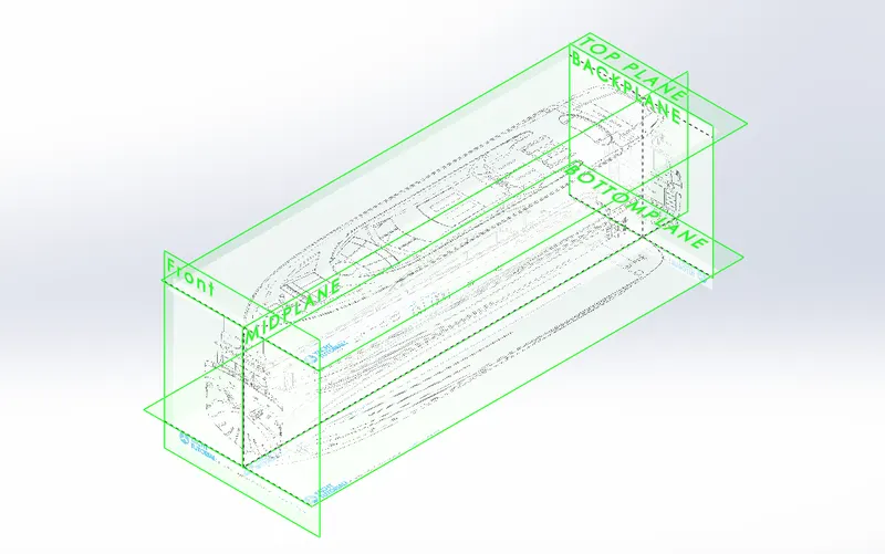
BLUEPRINT SETUP:
A blueprint is the reproduction of a technical drawing. An accurate blueprint is the best way to document your design ideas with accuracy, therefore bringing your ideas to reality. An auto body shop blueprint is an assessment of the state of your car and any required vehicle repairs. It involves an in-depth process to analyze your car's interior and exterior, often involving removing some panels to access the inner structure as well as using some electronic diagnostic tools.
propeller:
A propeller is a rotating fan-like structure that is used to propel the ship by using the power generated and transmitted by the main engine of the ship. Hidden under the waterline, out of sight and out of mind, many take the performance and efficiency of their yacht propellers (or 'props') for granted. Yacht propellers can take a beating, even in the best sailing conditions.
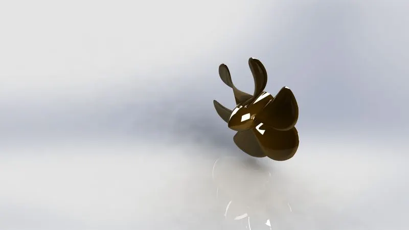
the command used to model:
- spline
- circle
- line
- revolve
- loft
- extrude cut
- reference plane
- circular pattern
- fillet
Radar:
Marine radars are X-band or S-band radars on ships, used to detect other ships and land obstacles, and to provide bearing and distance for collision avoidance and navigation at sea.A Radar (Radio Detection And Ranging) is an instrument that can detect surrounding objects using radio waves. Thus, in the maritime world, objects such as ships, buoys, or birds can be detected by Radars. The use of short-wavelength microwaves allows a very accurate measurement of the direction in which the object is detected and the distance at which it is located. In addition to the maritime domain, Radars have many other applications such as meteorology and aerial surveillance.
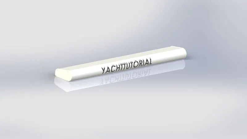
commands used to model:
- line
- text
- circle
- point
- extruded
- extrude cut
- sketch pattern
- fillet
- mirror
- split line
Hull:
The hull of a ship is the most notable structural entity of the ship. Define the hull, it can be said that it is the watertight enclosure of the ship, which protects the cargo, machinery, and accommodation spaces of the ship from the weather, flooding, and structural damage.

commands used to model:
- line
- spline
- circle
- rectangle
- arc
- slot
- 3d sketch
- sketch picture
- extruded surface
- revolved surface
- lofted surface
- surface trim
- surface knit
- delete face
- project curve
- chamfer
- fillets
- reference plane
- split
- split line
- mirror
Garage door:
Like the outer doors in the house, the garage door shares a similar purpose—protection and security from external factors. Commonly, the garage door protects cars and vehicles like bicycles from being bathed under the sun's scorching heat and the bitter cold of winter.
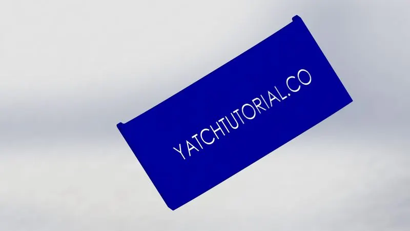
The command used to model:
- line
- spline
- circle
- text
- extrude cut
- reference plane
- fillet
- shell
- mirror
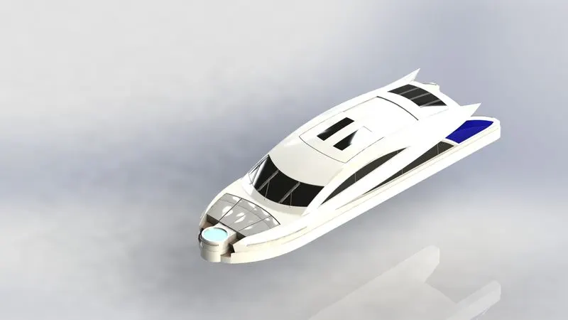
superstructure:
A superstructure is a decked structure on the freeboard deck, extending from side to side of the ship or with the side plating not being inboard of the shell plating more than 4% of the breadth (B). A raised quarter-deck is regarded as a superstructure. (Raised quarter-decks are often associated with smaller ships. A superstructure (the bridge deck) is an upward extension of an existing structure above a baseline called ground level and it usually serves the purpose of the structure's intended use. Building parts located above the ground such as the column, beam, floor, roof, etc.
commands used to model:
- sketch picture
- 3d sketch
- line
- spline
- circle
- rectangle
- center point arc
- extruded surface
- swept surface
- ruled surface
- knit surface
- trim surface
- extend surface
- filled surface
- lofted surface
- revolved surface
- fillet
- chamfer
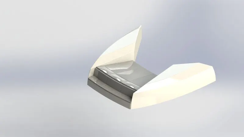
front seat:
commands used to model:
- sketch picture
- 3d sketch
- line
- spline
- circle
- rectangle
- center point arc
- extruded surface
- swept surface
- ruled surface
- knit surface
- trim surface
- extend surface
- filled surface
- lofted surface
- revolved surface
- fillet
- chamfer
- extruded cut
- dome
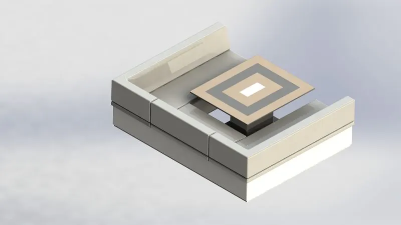
Middle seat:
the middle seat in our model was placed just behind the superstructure . it is provided with a luxury table to dine out. it can also be used to have casual meetings with co-passengers.
commands used to model:
- line rectangle
- extruded boss base
- chamfer
- fillet
- mirror
- reference plane
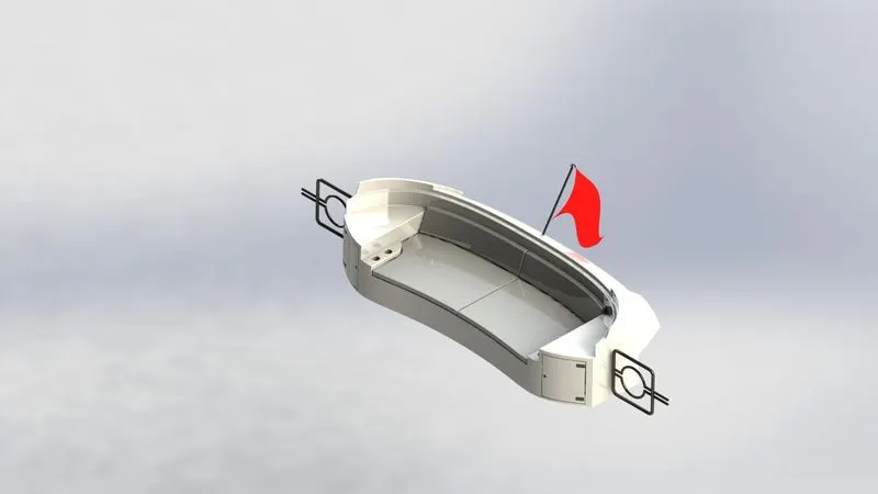
Rear seat:
the rear seat is placed at the end of the deck surface. the rear seat consists of locker racks and steel doors for our stairs. the flag was also placed behind the rear seat since it's the end part of our yatch.
commands used to model:
- 3d sketch
- line
- spline
- circle
- rectangle
- center point arc
- extruded surface
- swept surface
- ruled surface
- knit surface
- trim surface
- extend surface
- filled surface
- lofted surface
- revolved surface
- fillet
- chamfer
- extruded cut
radar mast:
Radars send out electromagnetic waves similar to wireless computer networks and mobile phones. The signals are sent out as short pulses which may be reflected by objects in their path, in part reflecting back to the radar. When these pulses intercept precipitation, part of the energy is scattered back to the radar. The word "radar" is an acronym for "Radio Detection and Ranging." In simple terms, radar uses radio waves reflected off a moving object to determine its speed. With police radar, that moving object is your car. Radar units generate the waves with a transmitter.
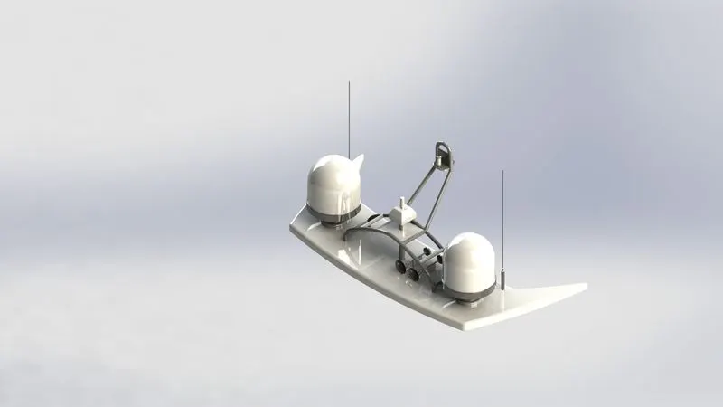
the command used to model:
- spline
- circle
- line
- revolve
- loft
- extrude cut
- reference plane
- circular pattern
- fillet
- dome
- swept
- mirror
- arcs
Assembly:
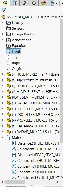
You can build complex assemblies consisting of many components, which can be parts or other assemblies, called subassemblies. For most operations, the behavior of components is the same for both types. Adding a component to an assembly creates a link between the assembly and the component. When SOLIDWORKS opens the assembly, it finds the component file to show it in the assembly. Changes in the component are automatically reflected in the assembly.
The FeatureManager design tree displays these items for assemblies:
- Top-level assembly (the first item)
- Various folders, for example, Annotations and Mates
- Assembly planes and origin
- Components (subassemblies and individual parts)
- Assembly features (cuts or holes) and component patterns
- Grouped components
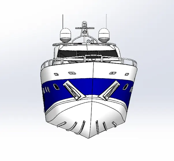
Front view
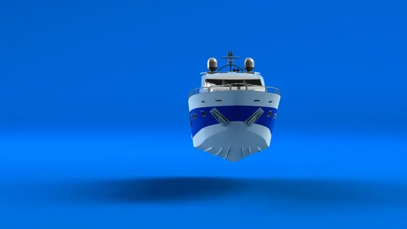
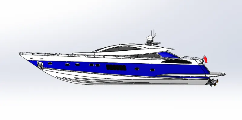
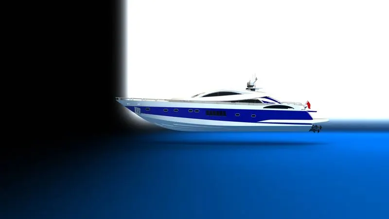
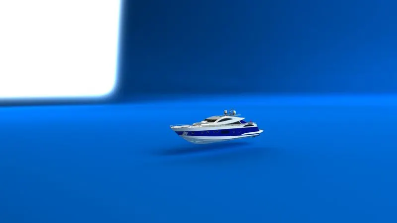
side view:
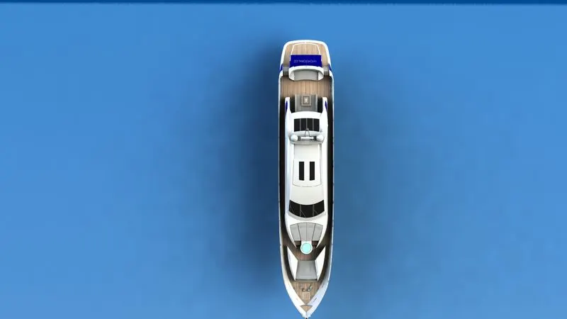
top view:
camera view:
Rendering:
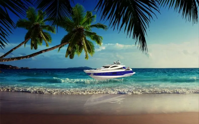
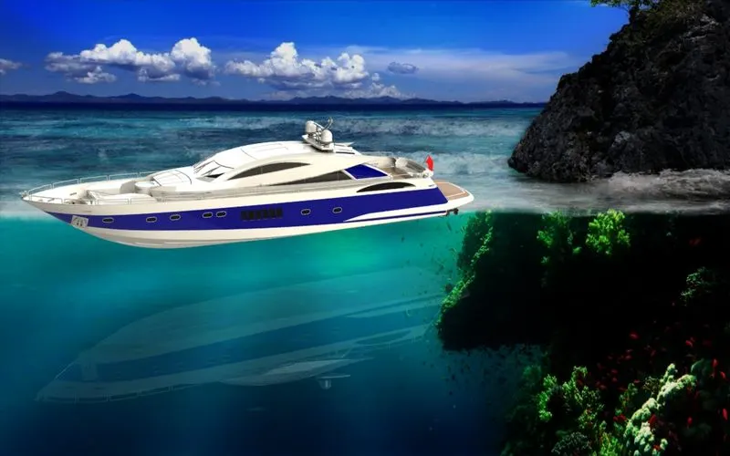
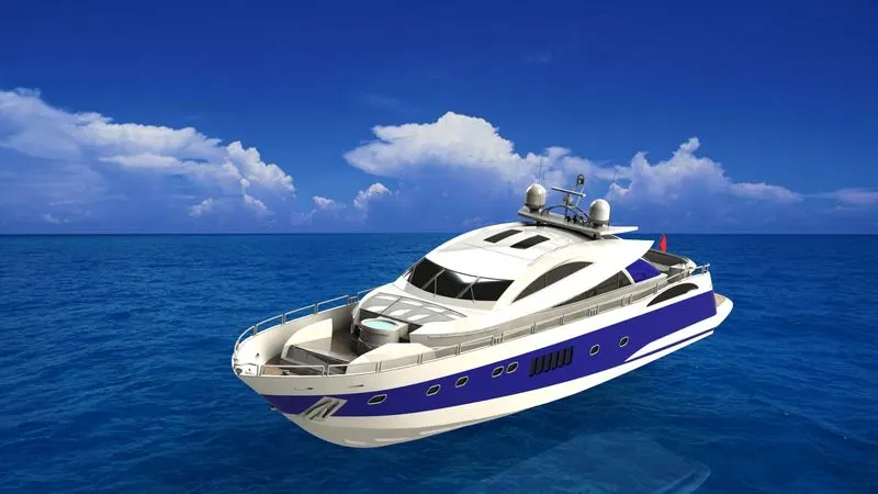
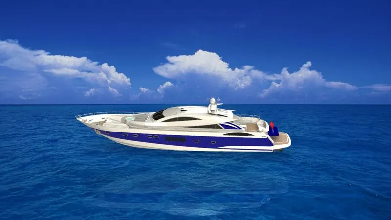
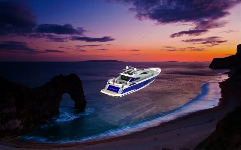
PhotoView 360 is a SOLIDWORKS add-in that produces photo-realistic renderings of SOLIDWORKS models. The rendered image incorporates the appearances, lighting, scene, and decals included with the model. PhotoView 360 is available with SOLIDWORKS Professional or SOLIDWORKS Premium. You can use RealView and Ambient Occlusion to add realism to your models without rendering. You can use PhotoView 360 within SOLIDWORKS or Visualize, a standalone suite of tools, to produce photo-realistic renderings of your models.
conclusion:
Through this project, I have learned......
- how to design a part of a model with proper 3d sketching and dimensioning.
- how to make a fully defined sketch
- how to model a part or component using different features like surface modeling and solid modeling etc.
- how to make on assembly by using proper mates.
- how to make a photo-realistic view of a model by using photoview360 and Solidworks visualize.