Wiring harness design in CATIA V5 - 3D modeling Week 4 Challenge
Above picture shows the 2D schematic layout of the required harness.
The following Deutsch connectors are used in this harness:-
- DT06-4S (QTY-2)
- DT06-6S (QTY-1)
- DT06-2S (QTY-2)
- DT06-8S (QTY-1)
STEP-1
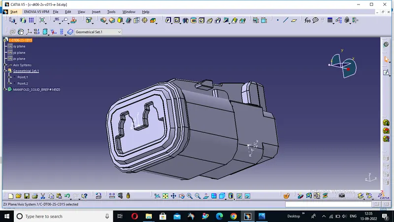
Completely define the geometrical and electrical parameters of all connectors in the electrical part design workbench in CATIA V5.
- DT06-2S (QTY-2)
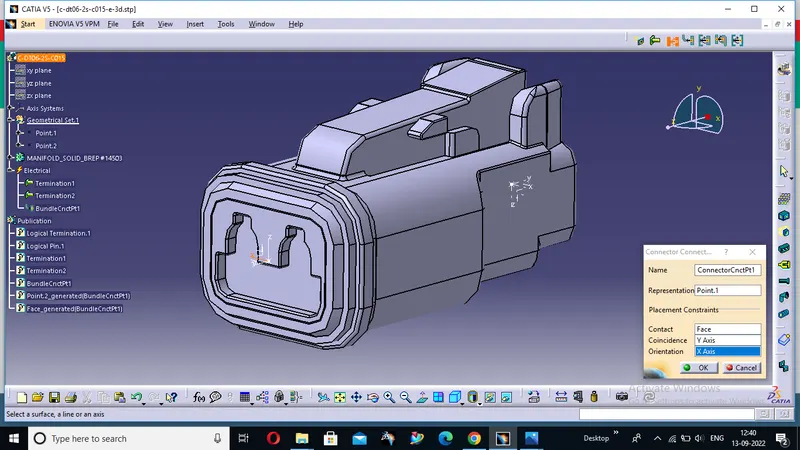
- DT06-4S (QTY-2)
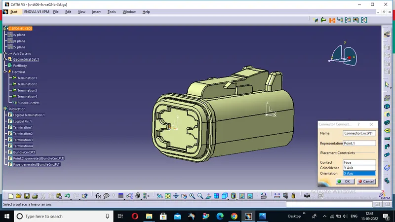
- DT06-6S (QTY-1)
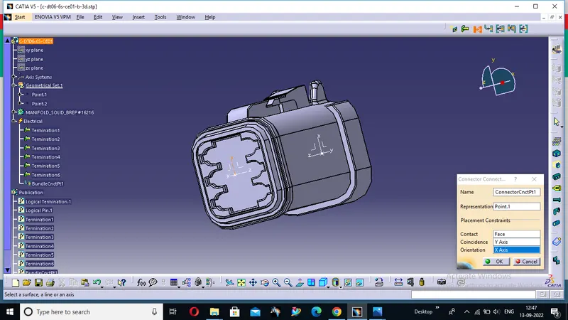
- DT06-8S (QTY-1)
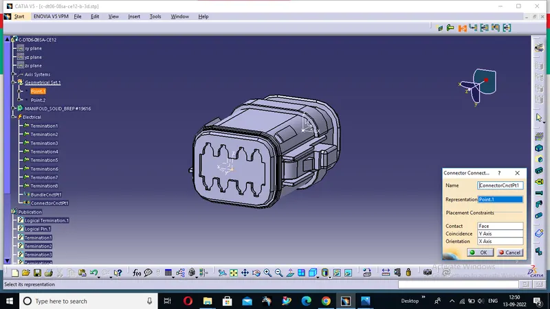
Above picture shows all the connectors which are geometrically and electrically defined.
STEP-2
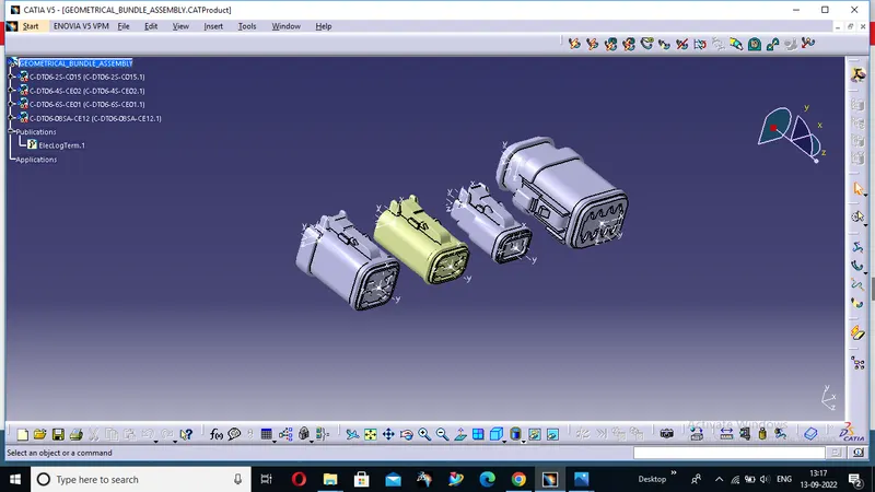
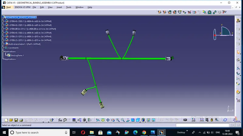
Then we create a product file in assembly design and name it as "GEOMETRICAL BUNDLE ASSEMBLY" in which we add all the connectors which are electrically defined,after adding all the connectors we convert mechanical assembly design into electrical assembly by using "Geometrical Bundle" command.
This is the given assembly work bench :--
STEP-3
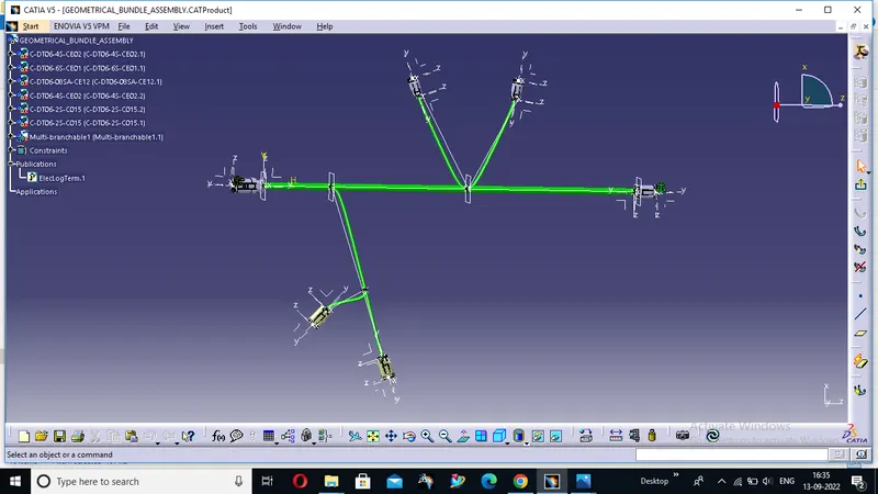
Orient and locate all the connectors approximately in the required location in assembly workbench.
Creating Bundle segments and branching points between the connectors.
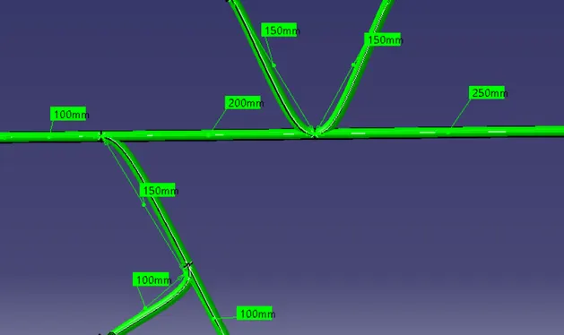
First create bundle segment between the connectors DT06-8SA and DT06-6S.Here assumed harness bundle diameter as 12mm.
Then create the branch points and add the segments to join the two DT06-4S connectors.Here assumed harness bundle diameter as 5mm.
Similarly create another branch point and add the segments to join the two DT06-2S connectors.Here assumed harness bundle diameter as 5mm
THE CATPART DATA IS GIVEN BELOW
SEARCH FOR GEOMETRICAL BUNDLE