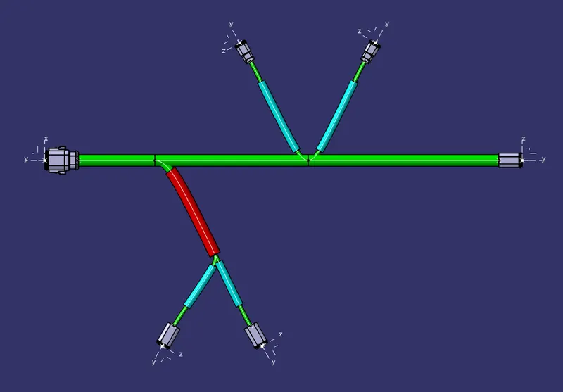
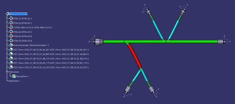
Wiring harness design in CATIA V5 - 3D modeling Week 4 Challenge
OBJECTIVE: Route the harness layout in the Electrical workbench. Make assumptions for harness bundle diameters. Add protective covering on all branches connected to DT06-2S & DT06-4S connectors. Keep end extremity at 30mm (from connectors end).
DATA GIVEN:
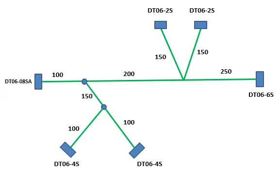
Wiring Harness Layout:
Connector:
- DT06-4S
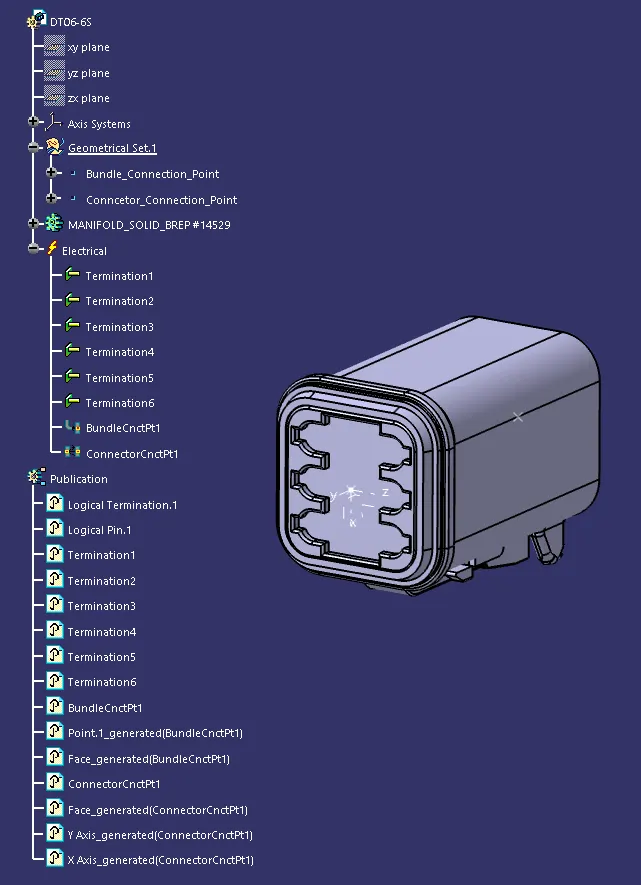
- DT06-6S
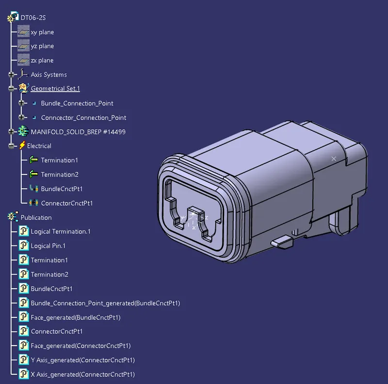
- DT06-2S
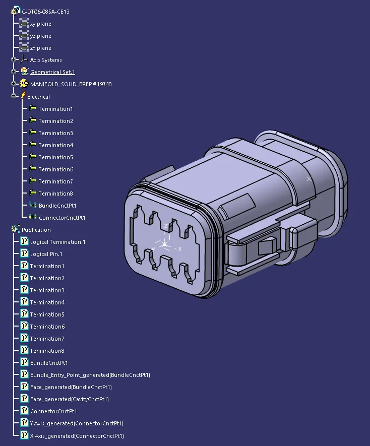
- DT06-08SA
PROCESS:
1. Download all the connectors and Import the step or igs file into the CATIA mechanical part workbench.
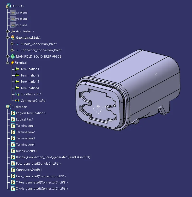
2. Define the Bundle Entry Point, Connector Connection Point, and Connector Connection Axis. Y-Axis should face the other mating part/direction and X-Axis should face the lock.
3. Now switch to the Electrical Part Design Workbench and define the connector using Define Connector Command with Name and No. of Terminals.
4. Define the Bundle Connection Point and the Connector Connection Point.
DT06-4S
DT06-6S
DT06-2S
DT06-08SA
5. Open a new Product file and all the connectors to it.
6. Arrange all the connectors according to the layout.
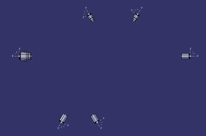
7. Connect DT06-08SA to DT06-6S and add branch points at 100 and 250.
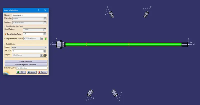
8. Connect the branch point at 100 to the DT06-4S connector and add another branch point at 150.
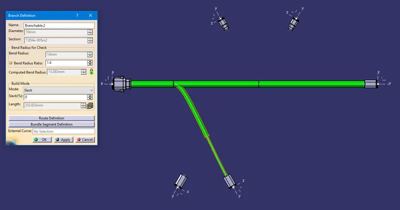
9. Connect the branch point at 150 to the other DT06-4S connector.
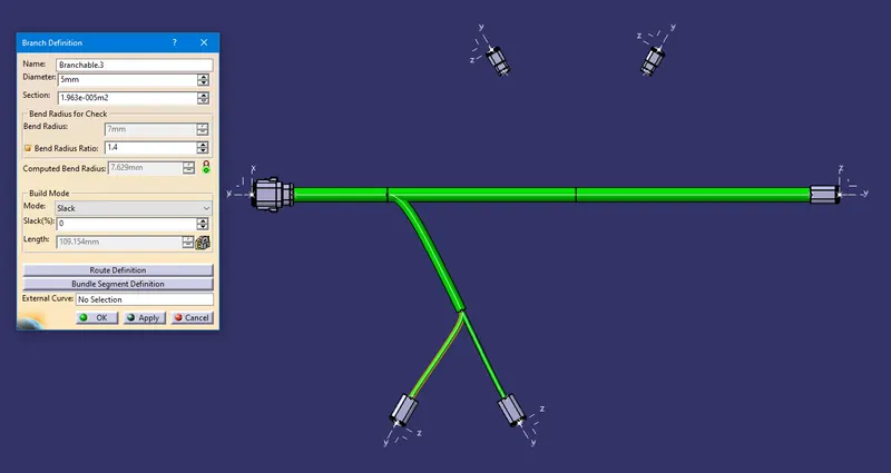
10. Connect the branch point at 250 to both the DT06-2S connectors one by one.
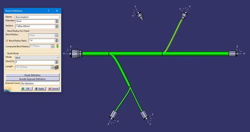
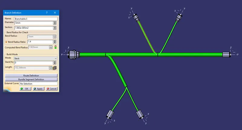
11. Now add the protective covering according to the diameter of the wire. Give end extremity at 30mm (from all connectors end).