Wiring harness design in CATIA V5 - 3D modeling Week 4 Challenge
Aim:
- Route the harness layout in the Electrical workbench based on the input.
- Add protective covering on all branches connected to DT06-2S & DT06-4S connectors. Keep end extremity at 30mm (from connectors end)
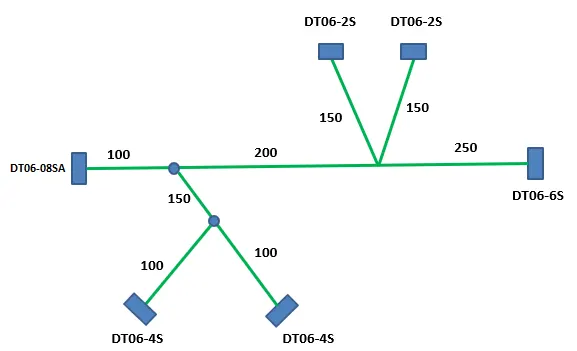
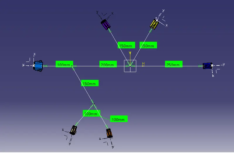
The above picture shows the 2D schematic layout of the required harness.
- DT06-4S (QTY-2)
- DT06-6S (QTY-1)
- DT06-2S (QTY-2)
- DT06-8S (QTY-1)
STEP-1:
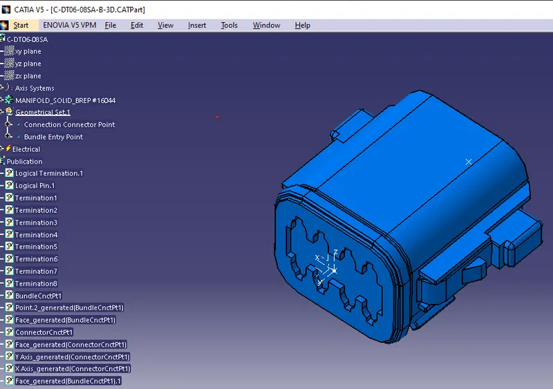
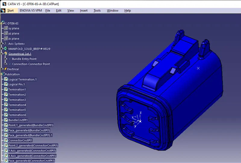
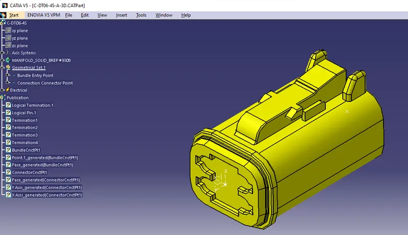
Completely define the geometrical and Electrical Parameters of all connectors in the Electrical Part Design workbench in CATIA V5.
DT06-08SA
DT06-6S
DT06-4S
DT06-2S
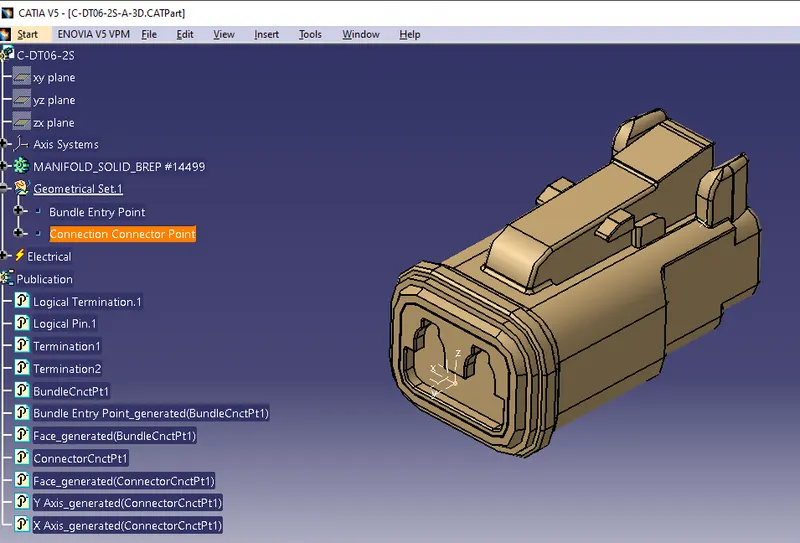
The above picture shows all the connectors which are geometrically and electrically defined.
STEP-2:
Then we create a product file in the assembly design and name it the "geometrical bundle assembly" in which we add all the connectors which are electrically defined, adding all the connectors we convert the mechanical assembly design into Electrical assembly by using the 'Geometrical Bundle' command.

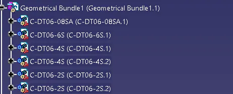
The above picture shows geometrical bundle assembly in electrically defined.
STEP-3:
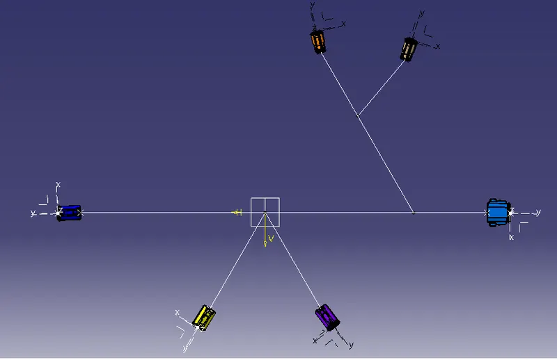
Orient and locate all the connectors approximately in the required location in the assembly design workbench.
STEP-4:
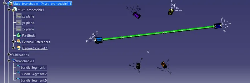
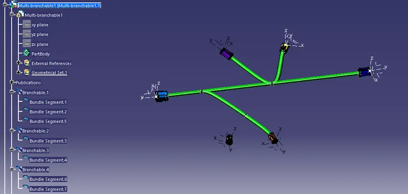
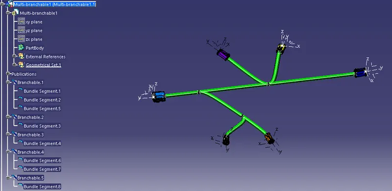
I am creating Bundle segments and using a multi-branchable between DT06-6S and DT06-08S-A.
First, create a bundle segment between the connectors DT06-6S and DT06-08S-A. Here assumed harness bundle has a diameter of 10mm.
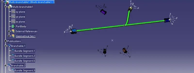
Then create the branch point and add the segments to join the two DT06-4S connectors. Here assumed harness bundle has a diameter of 10mm.
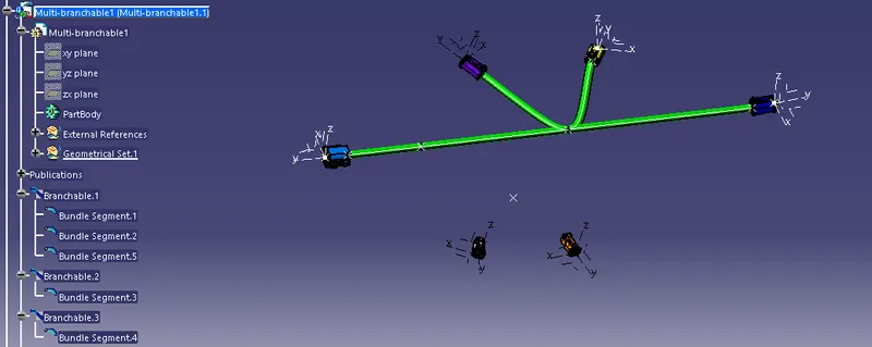
Similarly, create the branch point and add the segments to join the two DT06-2S connectors. Here assumed harness bundle diameter as the diameter of 10mm.
STEP-5:
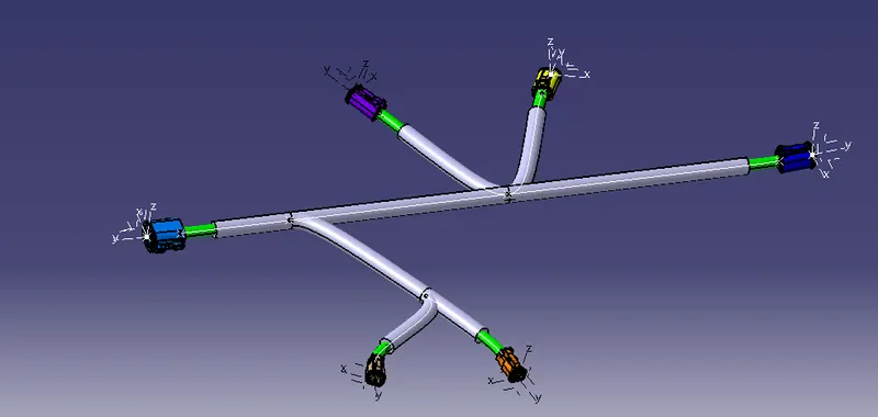
Here is the Corrugated Tube of 15mm as the harness bundle has a diameter of 10mm. Keep end extremity at 30mm away from the bundle entry point.
Add protective covering on all branches connected to DT06-2S & DT06-4S connectors. Keep end extremity at 30mm (from connectors end)
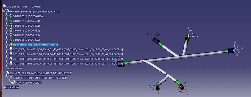
Final Wiring Harness Context:
Thus the wiring harness layout has been designed with the given inputs and added protective covering on all branches as shown in the below image.