Week 9 - Attachment Feature Creation - Challenge 2
AIM:
Create the boss and Dog House for the Centre console coin holder.
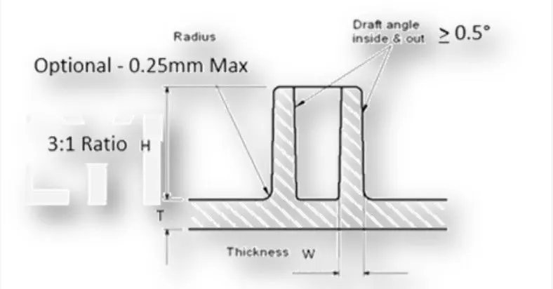
General Guidelines for Bosses:
- Draft - 0.5 degrees on walls of boss
- Thickness - Typically 40% * of the nominal wall at the base.
- Height to Diameter Ratio - 3:1
- Radii - 0.25mm maximum radii.
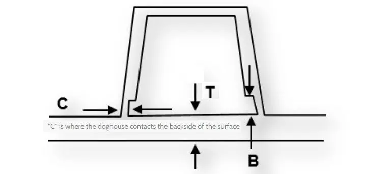
General Guidelines for Doghouse:
- Doghouse wall thickness at the intersection of the part wall ( C ) should be 40% or less than the main wall stock ( T ).
- Height of ( B ) should be between 3.0 – 6.0 mm
PROCEDURE FOR CREATING SCREW BOSSES :
STEP 1:
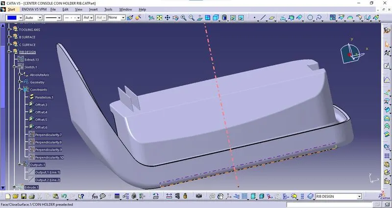
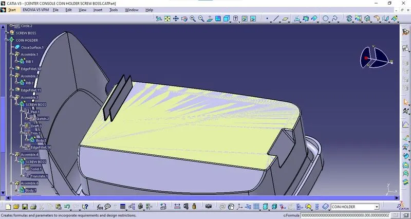
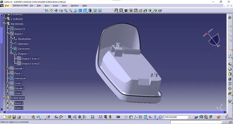
Extract the surface from the base of the coin holder to draw a sketch on it.
STEP 2:
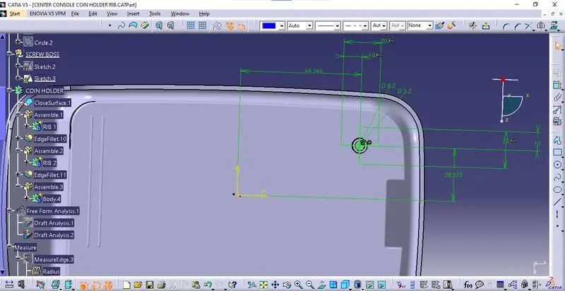
Sketch the Boss Circles.
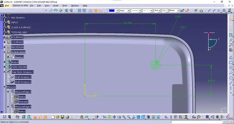
Let’s take an example of designing the screw boss for M6 screw for that the inner hole dia should be 5.2mm and outer dia should be -
Outer Dia of Boss = Inner Hold Dia + [(0.6 * Thickness of Component) * per Side of Wall]
= 5.2 + [(0.6 * 2.5) * (1+1)]
= 8.2`
STEP 3:
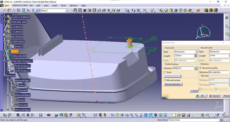
Pad the sketch from the part design.
Let's take the height of the boss to be 12mm and the second limit 1mm so there will be no possibility of a gap between the two parts.
STEP 4:
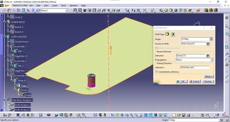
Draft the Pad to 0.5 degrees.
STEP 5:
Sketch the Boss’s walls.
STEP 6:
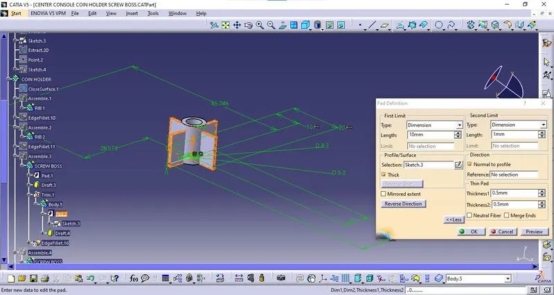
(Pad the sketch by switching the workbench to Part Design workbench inside Part Body)
Thickness of the walls should be 0.4*Thickness of components = 0.4 * 0.25 = 1mm.
STEP 7:
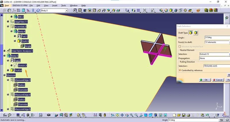
Draft the Boss’s Walls to 0.5 degrees.
STEP 8:
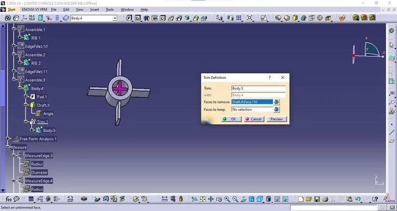
Assemble and Union Trim the Boss’s Walls to the Boss’s Circle body.
STEP 9:
Assemble the complete Screw Boss to the coin holder part body.
STEP 10:
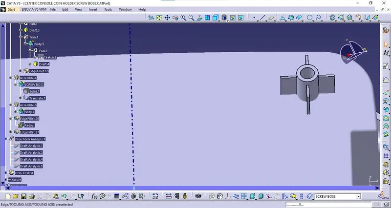
Give edge fillet to all the faces of screw boss with 0.25mm.
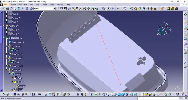
STEP 11: Duplicating and translation the Screw Boss to another Position.
- Copy the assembly of the screw boss.
- Paste it to the main tree of the Coin holder collector.
- Now translate it from the part workbench, translate it with values of X-Y-Z coordinates.
- Assemble it to the Main Part Body.
- Give edge fillets.
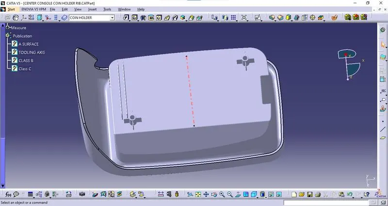
PROCEDURE FOR CREATING DOGHOUSE:
STEP 1:
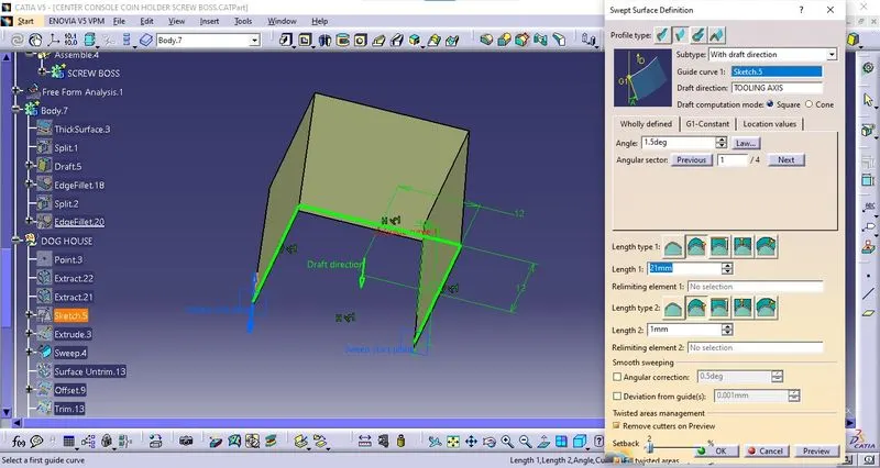
Sketch the Doghouse, we just required three lines with equal distance.
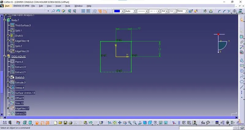
STEP 2: Sweep the sketch with the draft direction of tooling axis Y.
We don’t need to pad the sketch and give separate drafts, Sweep will help us to give a draft angle as well.
- Draft for the Doghouse is 1.5 Degrees.
- The minimum Width of the doghouse should be 12mm.
Let us take the height of the doghouse to 21mm and the second length limit to be 1mm.
STEP 3:
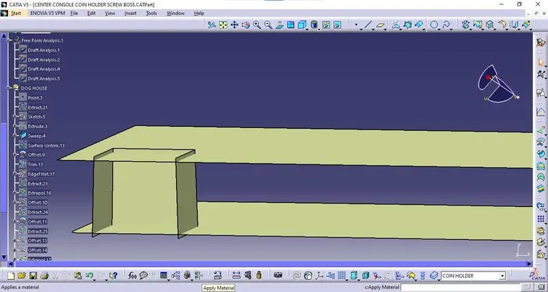
Offset the extracted surface to 20 mm to meet the height of the doghouse.
STEP 4:
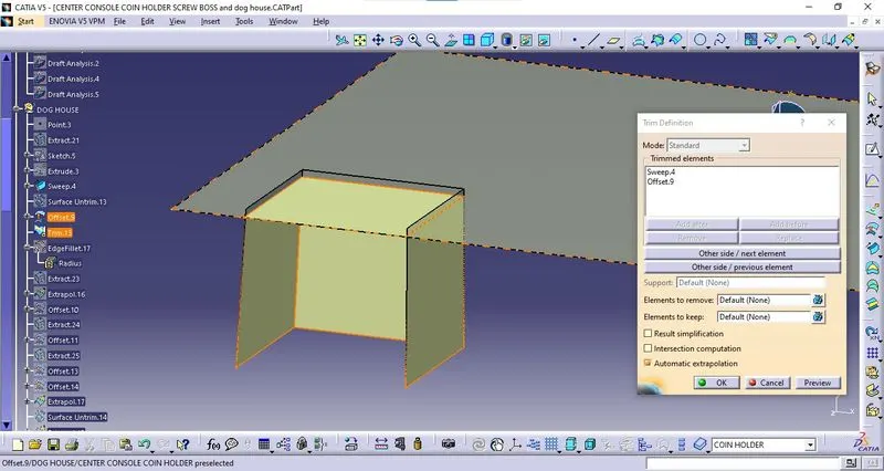
Trim the offset surface and sweep the surface to get the output of doghouse surfaces.
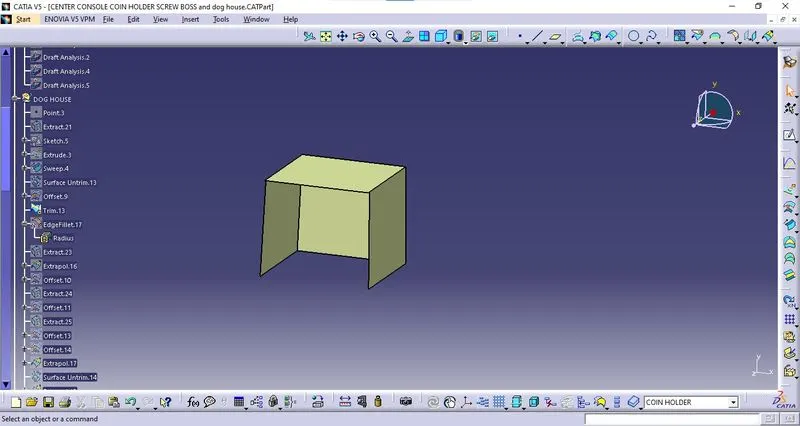
We can see the Doghouse surface as below
STEP 5:
Take the extract of the base of the Coin Holder.
NOTE:
Always use the surface extraction from the A-class surface, Taking extract from the solid part body may create a problem of deletion of some feature when we deactivate some assembly or part body.
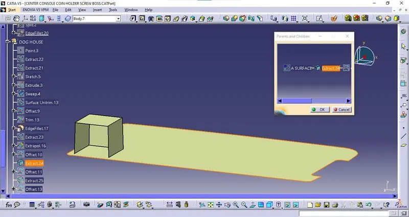
STEP 6:
Offset the extracted surface to 2.5mm to meet the thickness of the component.
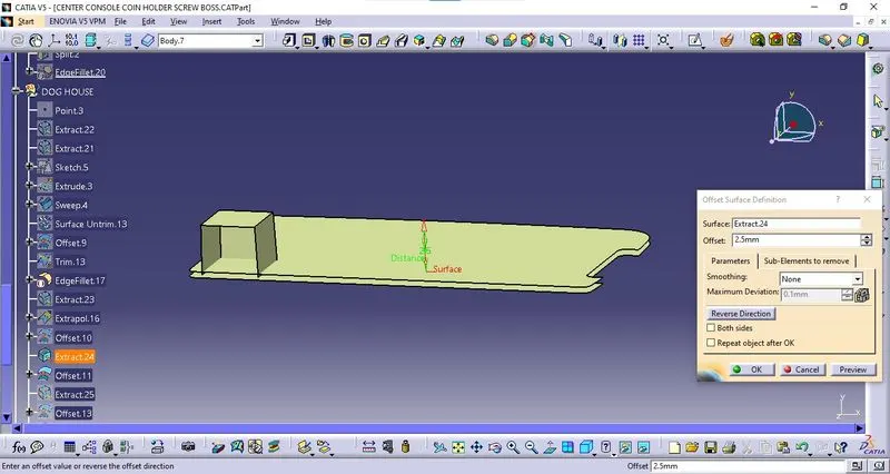
STEP 7:
Switch to part design and thicken the surfaces to 2mm.
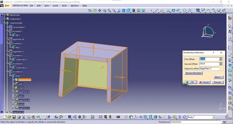
STEP 8:
Extract the backside of the doghouse surface. and Extrapolate by 10mm.
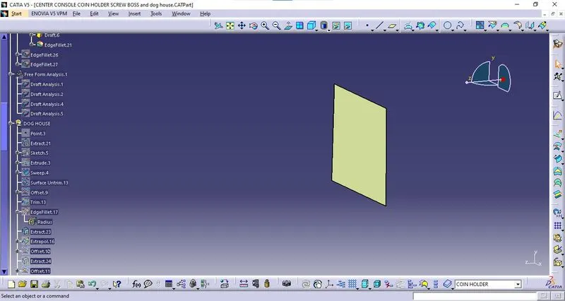
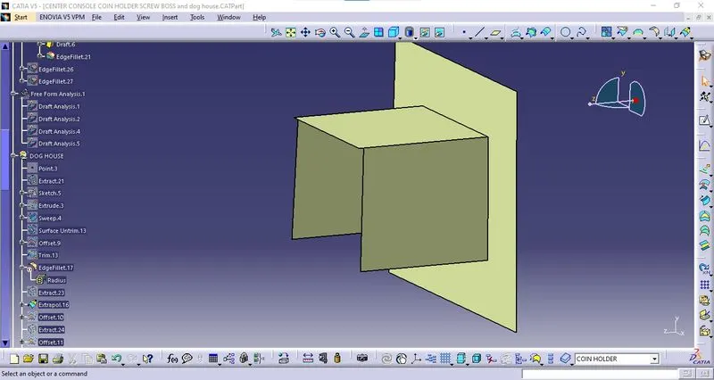
STEP 9:
Offset it to 22 mm on the front side of the doghouse.
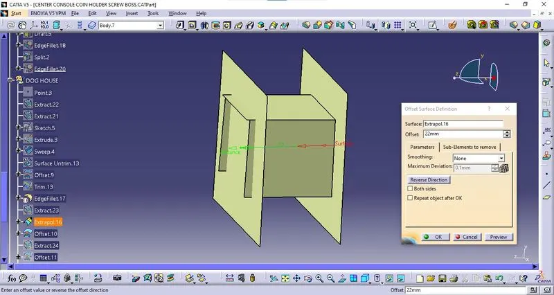
STEP 10:
Use split option in part design split the offset surface toward the doghouse.
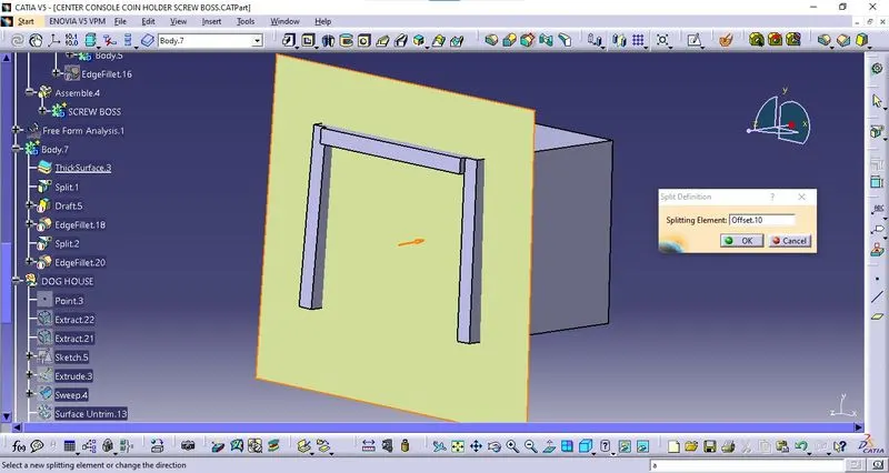
We can see the Doghouse part body as below-
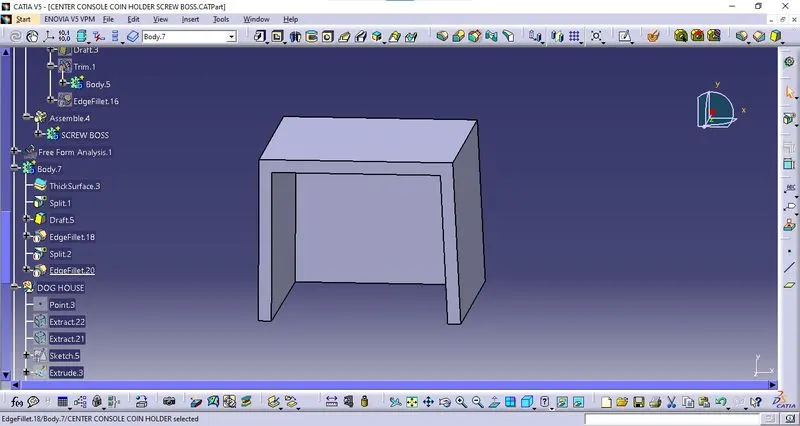
STEP 11:
Draft the inside three walls of the doghouse to o.5mm.
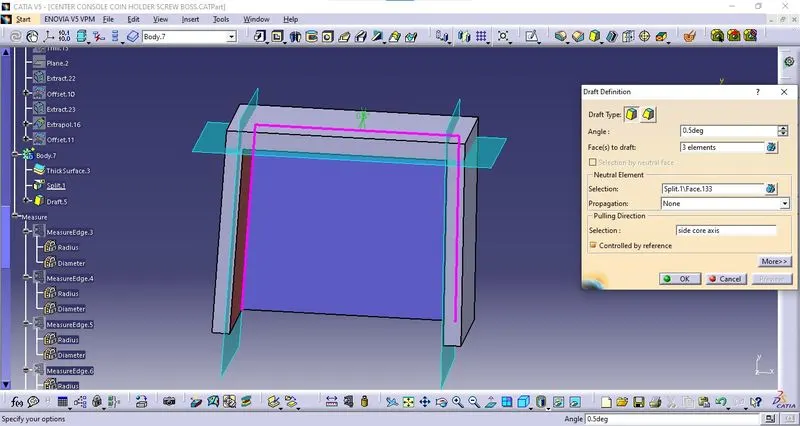
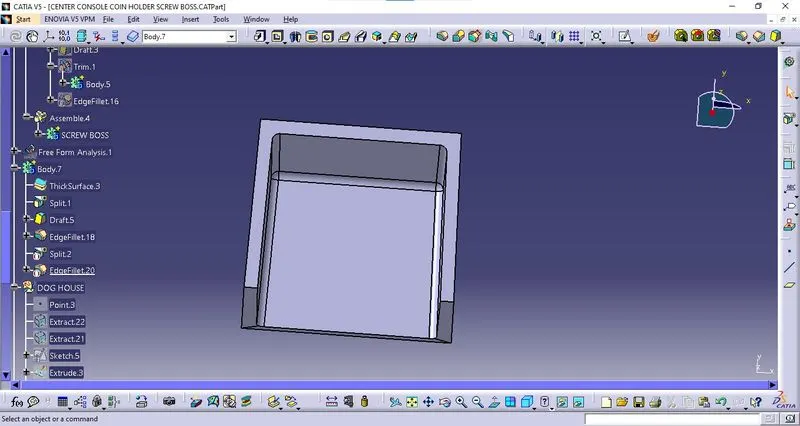
STEP 12:
Give edge fillet of 1mm to the inside edges.
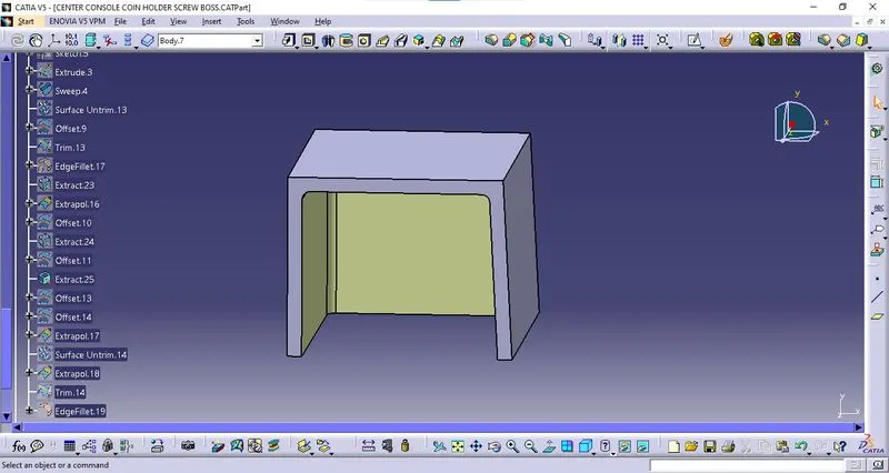
STEP 13:
Extract all the inside surfaces of the doghouse.
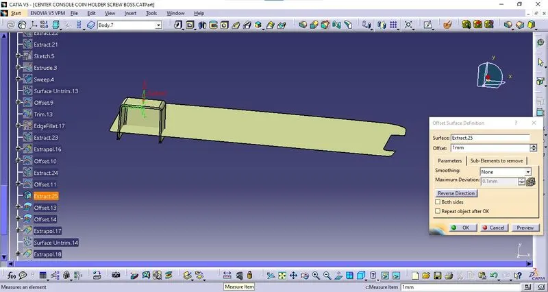
STEP 14:
Offset the extracted surface to 1mm
Extrapolate all the edges to 3mm
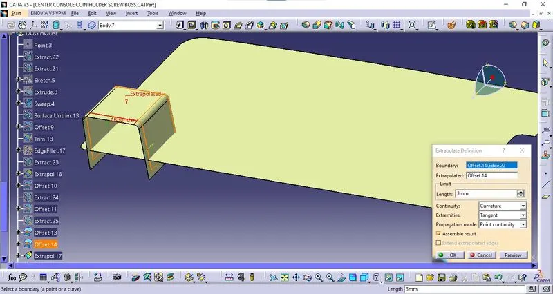
STEP 15:
Class A base surface the offset surface to 4mm towards the doghouse.
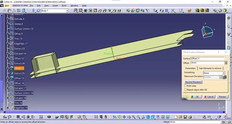
extrapolate the edges with a 3mm.
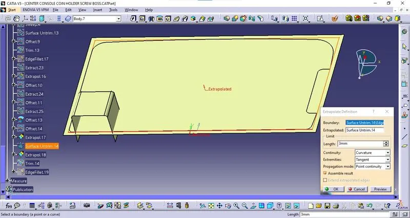
STEP 16:
Trim both surfaces.
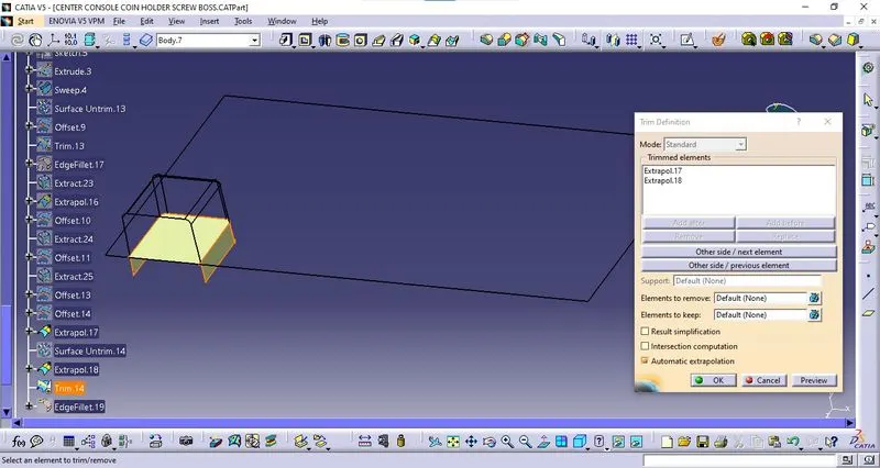
STEP 17:
Use the split option in part design, split the trimmed surface towards the doghouse.
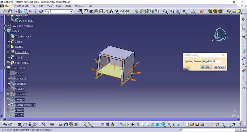
We can see undercut portion in doghouse part body as below-
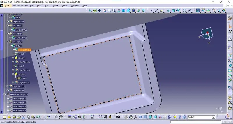
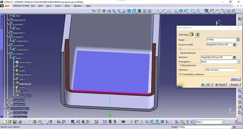
STEP 18:
Draft the undercut thin wall face to 0.5 degrees.
STEP 19:Give edge fillet to the edge of the drafted face of 0.5mm.
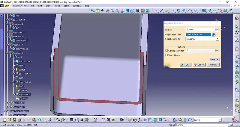
STEP 20: Give edge fillet on the outside edges of the doghouse.
- The inside edge of the doghouse is 1mm
- The thickness of the doghouse is 2mm.
- Outside edge = Inside edge + Thickness of doghouse = 1mm+2mm = 3mm.
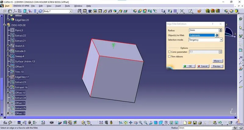
We can see the final doghouse part body as below-
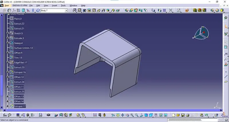
STEP 21:
Assemble the doghouse to the main coin holder part body.
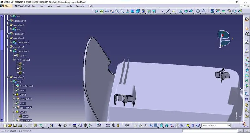
STEP 23: Duplicating (Rotating and Translating) the assembly of screw boss and doghouse to another Position.
- Copy the assembly of the screw boss and doghouse.
- Paste it to the main tree of the Coin holder collector.
- Rotate it from the part workbench, rotate the assembly to 135 degrees.
- Translate it from the part workbench, translate it with values of X-Y-Z coordinates.
- Assemble it to the Main Part Body.
- Give edge fillets.
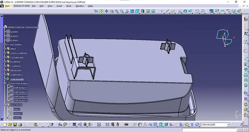
STEP 24: Give edge fillet to all the faces of all screw bosses and doghouse with 0.25mm.
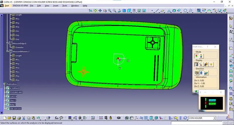
- We can see the final coin holder with screw boss and doghouse part body as below-
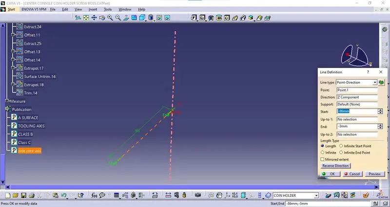
TOOLING AXIS TOWARDS Z DIRECTION :
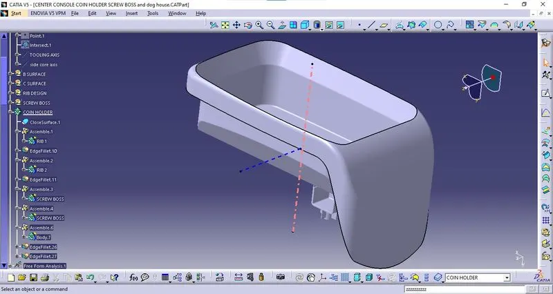
We can see all the tooling axes of the coin holder component.
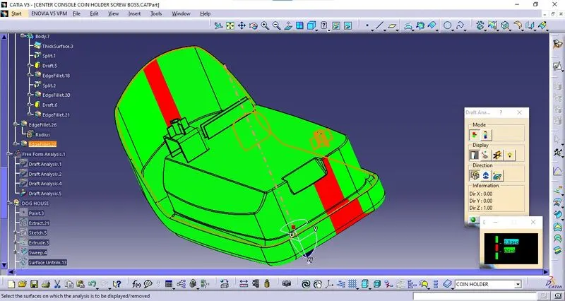
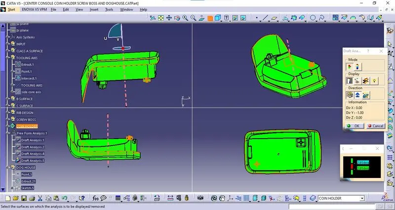
PROCEDURE TO CHECK DRAFT ANALYSIS :
STEP 2: Calling Draft Analysis.
Toolbar>Insert>Analysis>Feature Draft Analysis
STEP 3:
- Drag the compass from the draft analysis box on the tooling axis and place it properly.
- Click on locks so the compass will get locked to the tooling axis.
- Click anywhere on the component.
- Click OK.
- Analysis of the colour of the failing and passing surfaces.
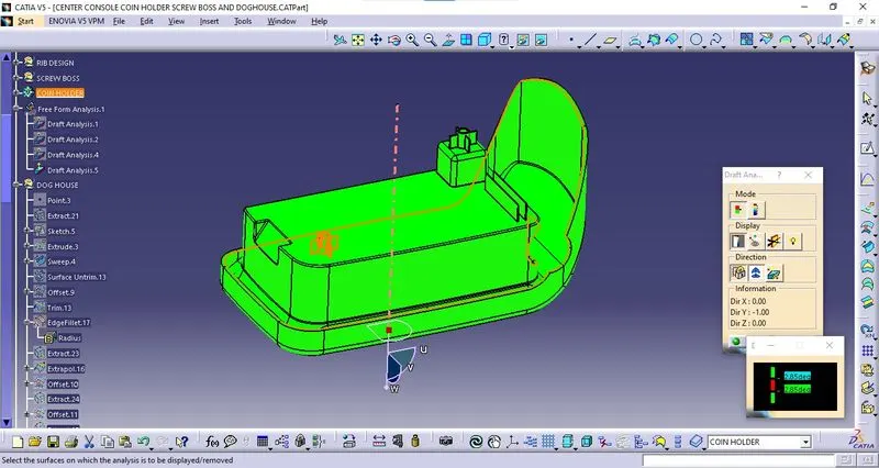
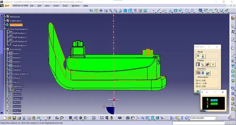
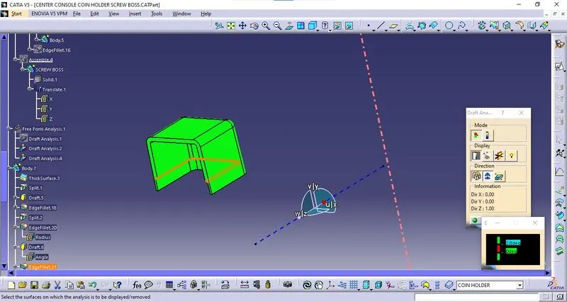
If a component is showing in the Green colour that means our component is ready for manufacture.
NOTE: If we find zero degree or negative degree failing colour, we can fix it by changing the draft angle, sweep direction, modifying properly tooling axis etc.
Feature draft analysis on Doghouse towards Z axis:
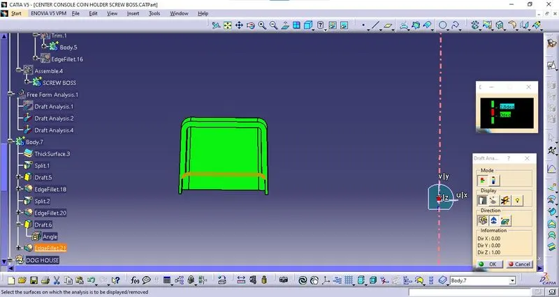
Feature draft analysis on coin holder component along Y axis: