Week 9 - Attachment Feature Creation - Challenge 1
AIM:
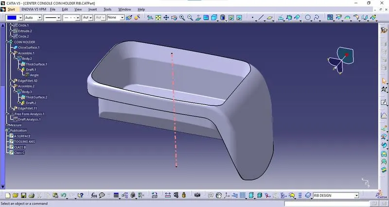
Create the rib for the Centre console coin holder.
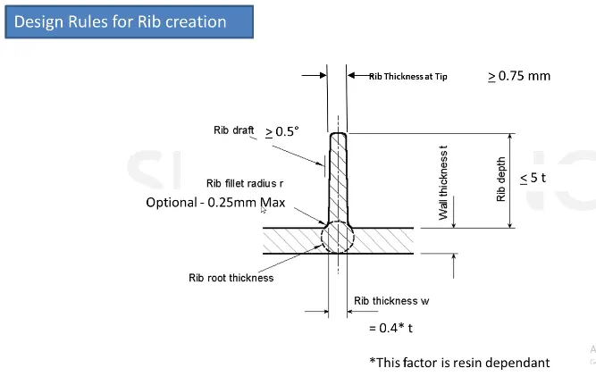
RULES OF CREATING RIBS:
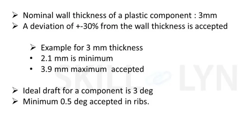
PROCEDURE FOR CREATING RIBS :
STEP 1:
Create an extract on the base surface.
STEP 2:
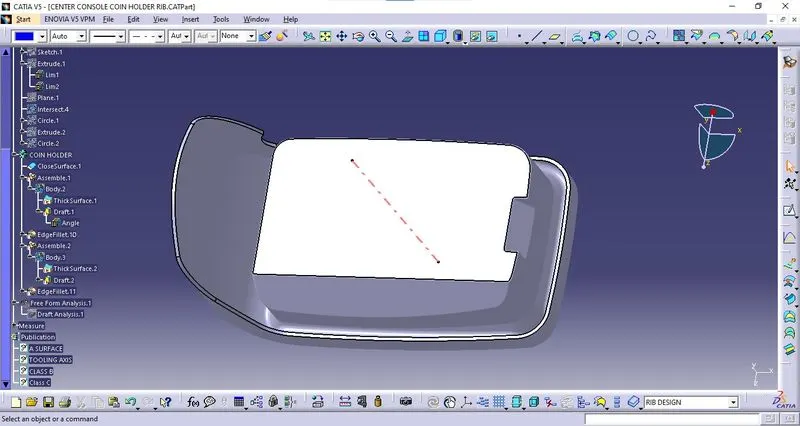
Sketch for creating rib.
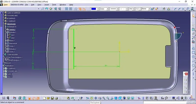
STEP 3:
Extrude the sketch.
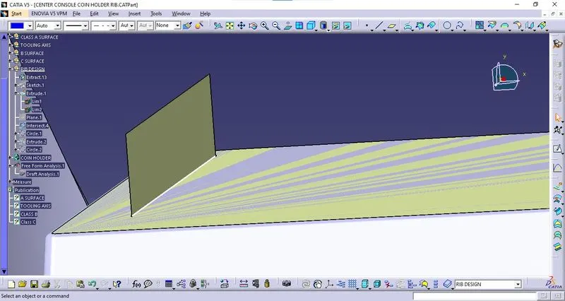
STEP 4:
Height of rib.
- The height of the rib should be 5*Thickness of components.
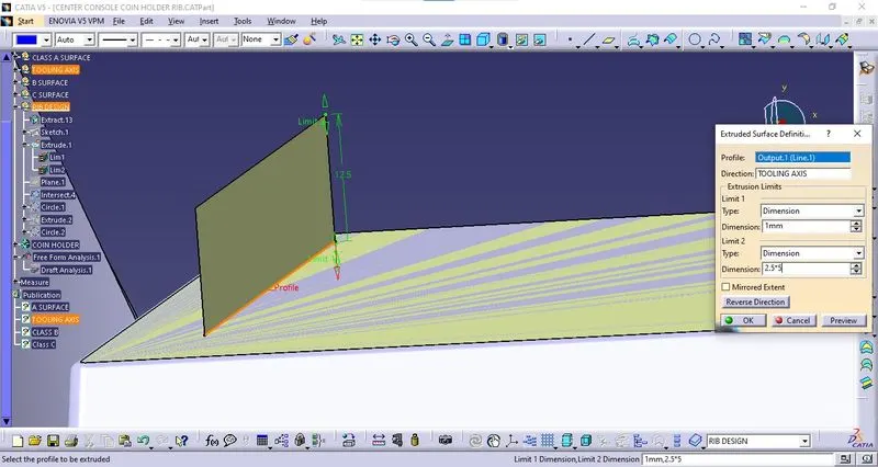
STEP 5:
The thickness of rib.
(Thicken the extract by switching the workbench to Part Design workbench inside Part Body)
- The thickness of the rib should be 0.4*Thickness of components.
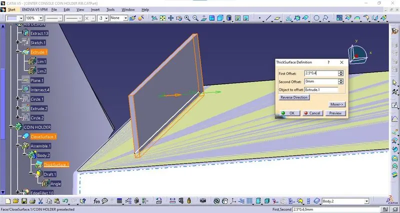
STEP 6:
Giving Draft to the Rib from all four sides.
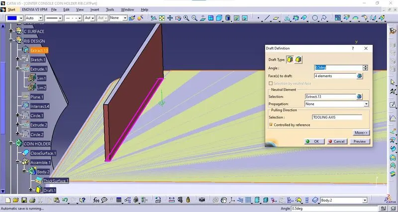
NOTE:
After giving draft, the top edge of the rib should be greater than 0.75mm
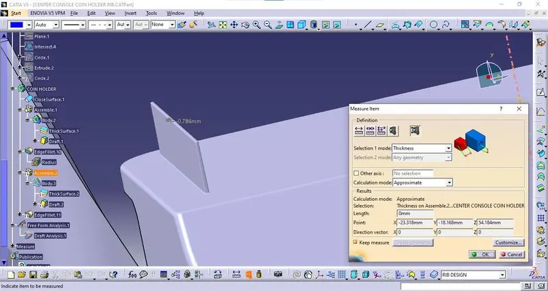
STEP 7:
Assemble the Rib Part Body inside the Main Part Body Component.
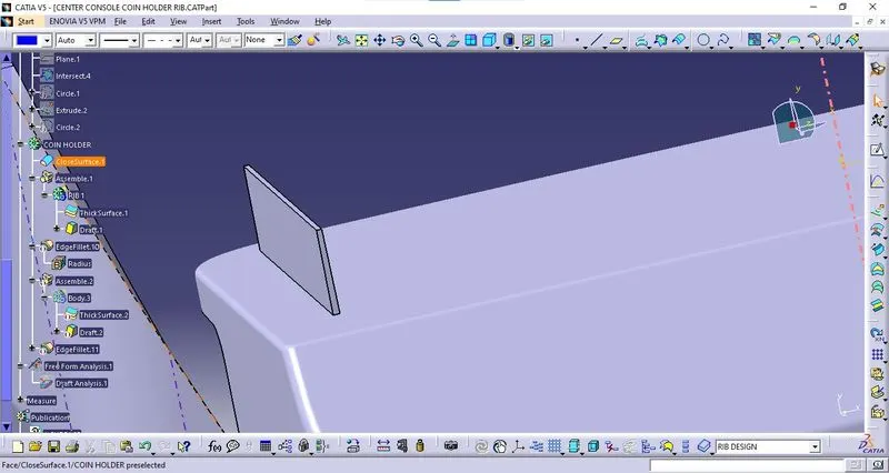
STEP 8:
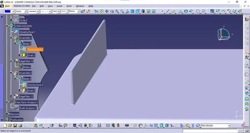
Edge Fillet of rib.
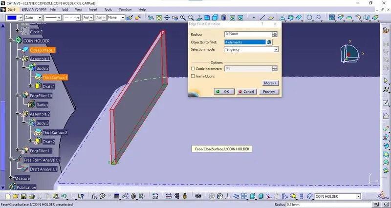
View after edge fillet.
STEP 9:
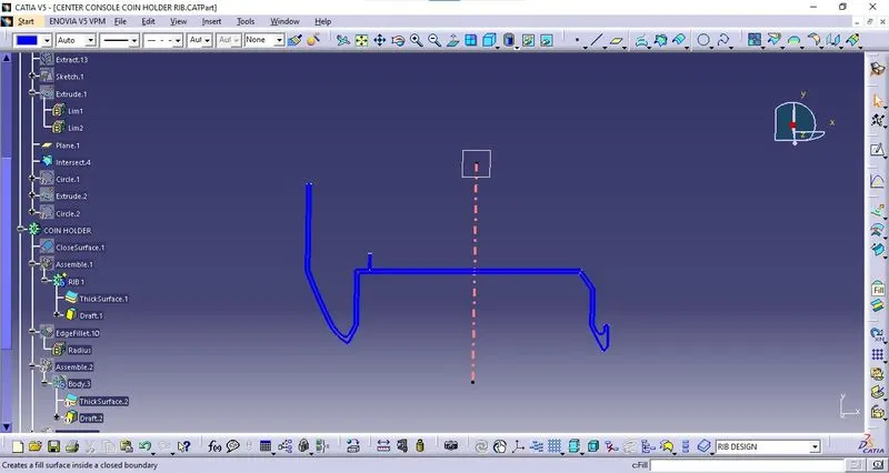
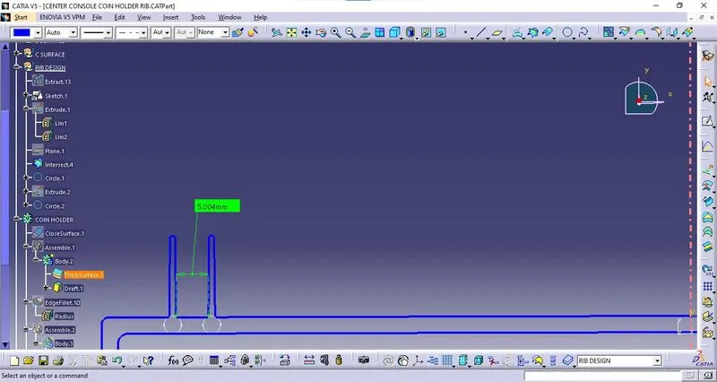
Intersect Coin Holder with Plane 1.
STEP 10:
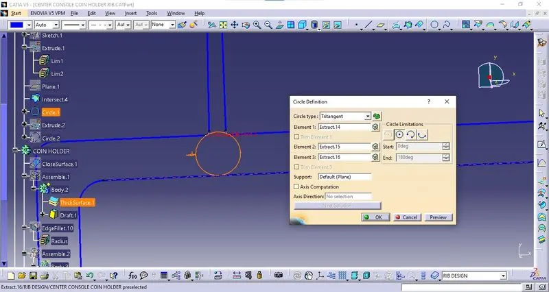
Checking Rib Root Thickness.
- Using Tritangent Circle from circle definition.
STEP 11:
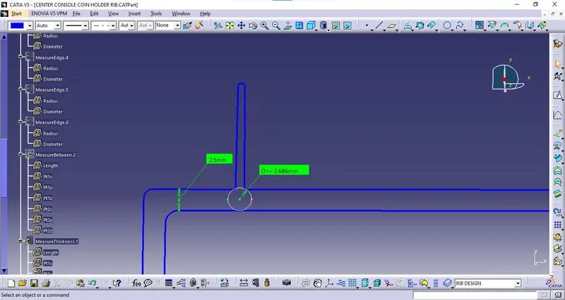
Checking Measurements of Rib Root Thickness.
Thickness with rib should be 30 % of the model thickness
STEP 12:
Creating more ribs.
Height (mm)/Gap (mm)=3:1
12.5/Gap=3:1
Gap=12.5/3
Gap=4.1
As 4.1mm is greater than 3
We can take a 5mm Gap.
- Repeat Step 1 to Step 8 to get a second Rib.
STEP 12:
To increase the number of ribs, give an output feature to the earlier sketch after offsetting 6mm (avoiding rib thickness to get a 5mm gap between every two successive ribs).
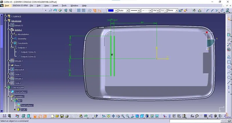
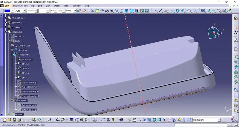
Result:
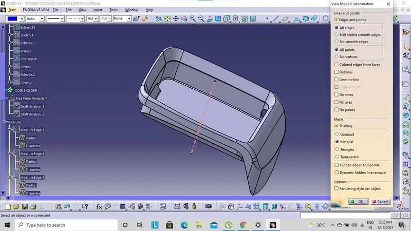
Procedure for Draft Analysis:
Step 1:
Change the view mode to material mode.
View mode>view mode customisation>tick material>ok.
STEP 2:
Calling Draft Analysis.
Toolbar>Insert>Analysis>Feature Draft Analysis
STEP 3:
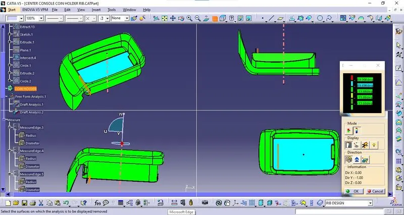
- Drag the compass from the draft analysis box on the tooling axis and place it properly.
- Click on locks so the compass will get locked to the tooling axis.
- Click anywhere on the component.
- Click OK.
- Analysis of the colour of the failing and passing surfaces.
If a component is showing in the Green colour that means our component is ready for manufacture.
Draft Analysis for Rib formation:
- The Draft Analysis command enables you to detect if the part you drafted will be easily removed.
- This type of analysis is performed based on colour ranges identifying zones on the analysed component where the deviation from the draft direction at any point, corresponds to specified values.
- This rule of thumb applies to parts with mould depths of up to 1 inches.
- Design for manufacture is one of the easiest ways to improve the quality and efficiency of your injection molding process, and it never hurts to stay up to speed on all injection moulding best practices.
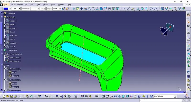
Checking feature draft analysis on the final part body:
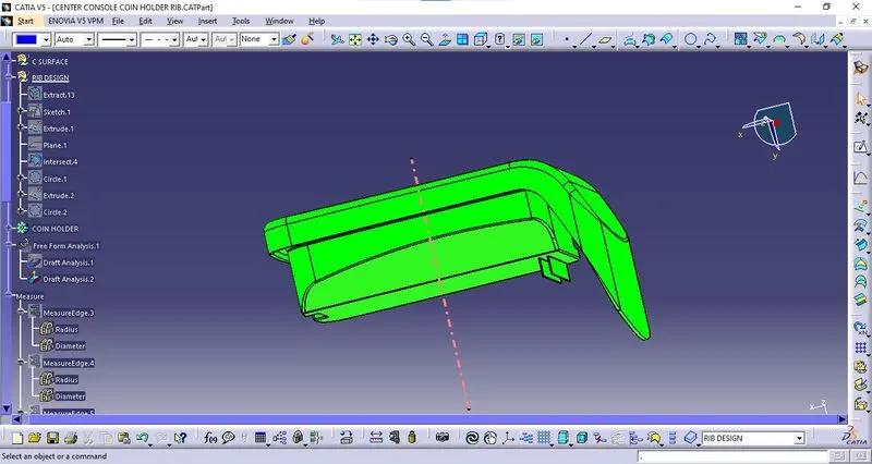
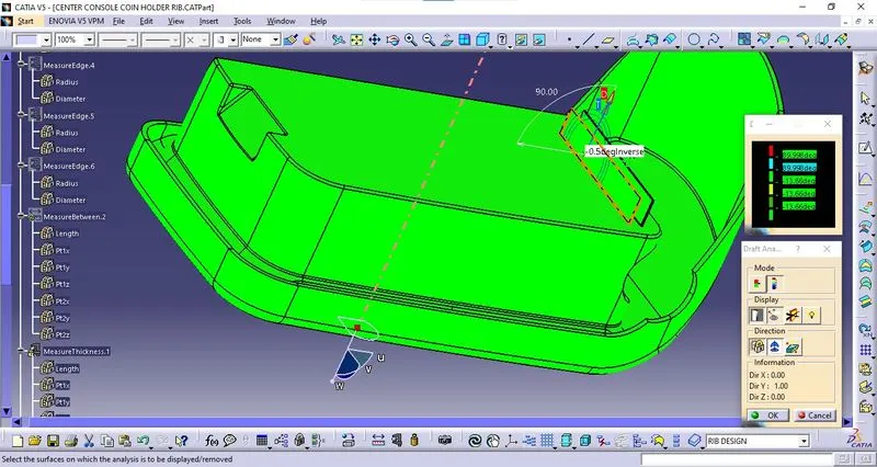
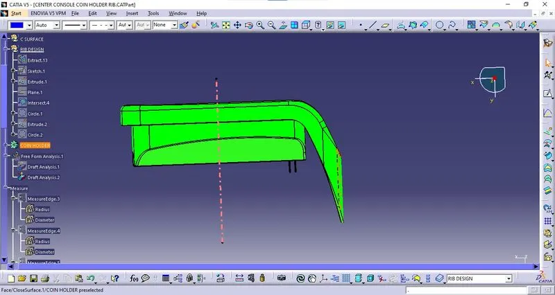
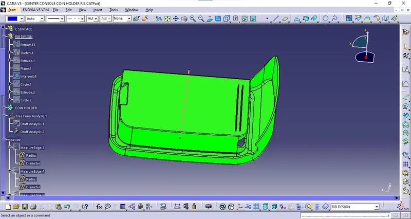
Screenshots of the completed design in various orientations: