Week 8 - Challenge 1 - Draft Analysis on a Fan Cover
Aim:
- To perform the draft analysis of a fan cover using CATIA V5.
Procedure:
Steps involved:
A)Determining and making the Tooling Axis:
1) Checking the boundary :
- The class A Surface is first checked for its boundary to find if there is any gaps or opening or discontinuity in the boundary.
- To ensure that there is no gaps between the two surfaces.
Insert the Tooling Axis Geometry:
- To start with position sketch of a hole boundary
- To Insert the axis system and the ensure that not current.
Dummy Tooling Axis:
- To create the dummy tooling axis with help of the point created earlier.
Intersect with zx plane:
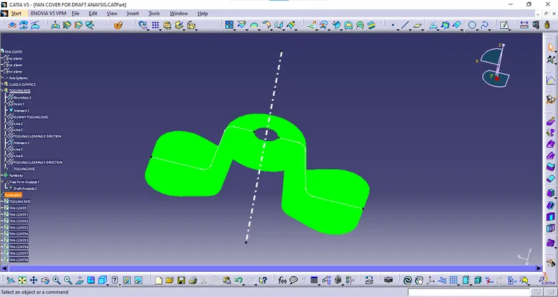
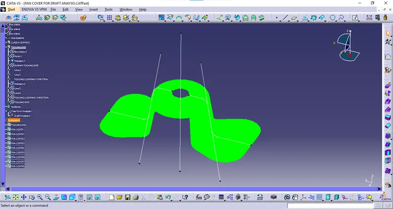
- I will take the zx plane intersect with the fan component and as a result to get the two lines.
- I will take the two lines and two lines are bisecting with the help of the created point.
- it represents the mid line is created and the two lines are bisecting to form tooling clearing x direction.
Intersect with yz plane:
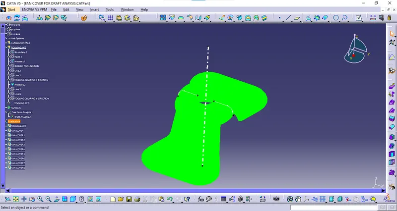
- I will take the yz plane intersect with the fan component and as a result to get the two lines.
- I will take the two lines are bisecting with the help of the pont.
- It represents the mid line is created and two lines are bisecting to form tooling clearing y direction.
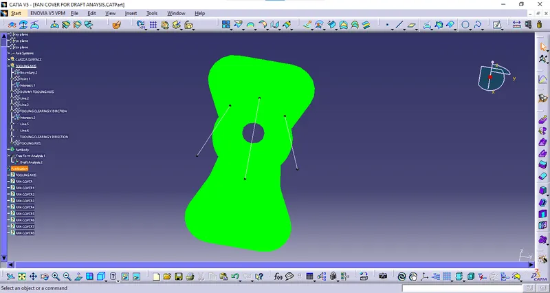
Creating the Tooling Axis:
- Tooling clearing x direction and tooling clearing y direction are bisecting with the help of the point .
- Finally to get the tooling axis and once it done tooling axis created.
Publishing the fan cover and the tooling axis:
- Publishing elements in CATIA V5 is used for various purposes.
- It easily visible the fan cover and tooling axis
- It helps to make the references of the part as a datum entity of the part.
Perform Draft Analysis:
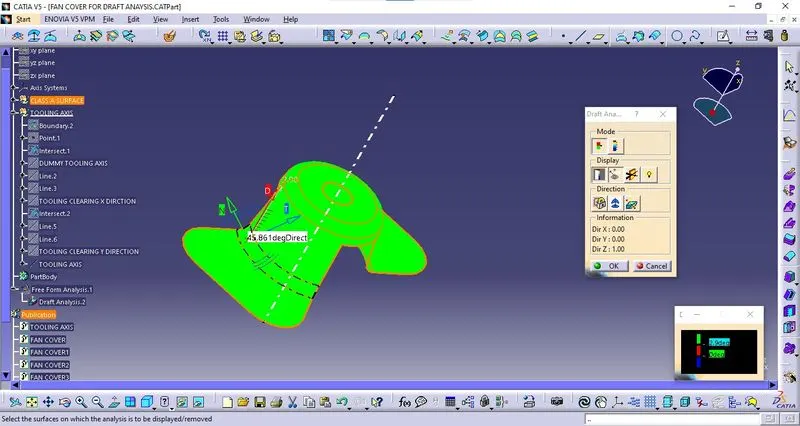
- Now, perform the draft analysis of the fan cover.
- To do so, go to tools > analysis > Feature Draft Analysis.
- This tool has three group of options namely; mode, display and direction.
- First, the second icon from the direction group is selected and the red dot in the compass is clicked and dragged to the part to be drafted.
- The line in the dragged element is matched with the tooling axis and it is locked using the first icon in the direction group. It will define the tooling axis direction and lock it
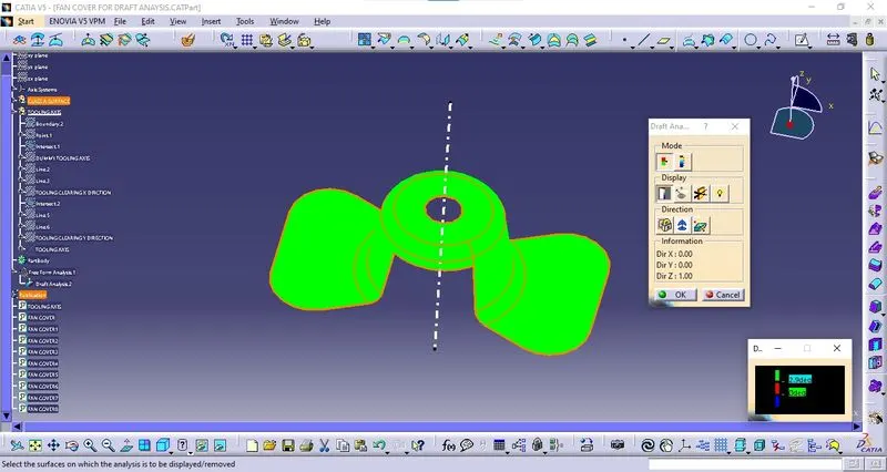
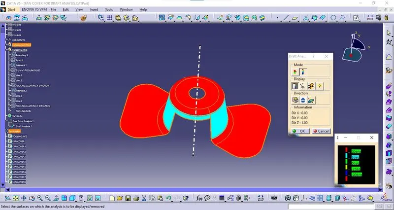
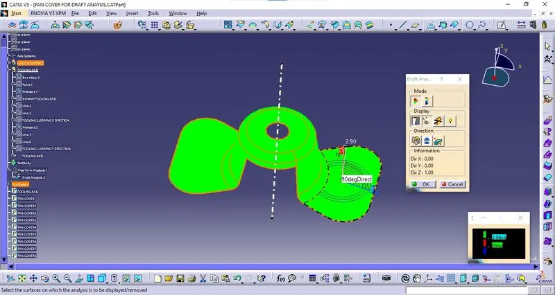
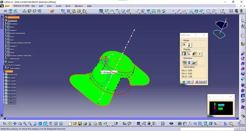
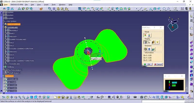
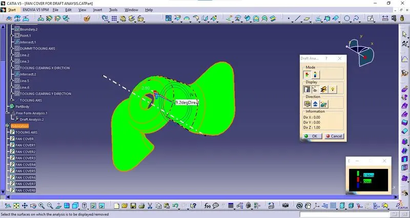
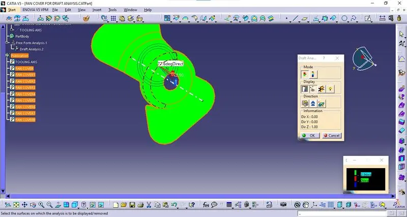
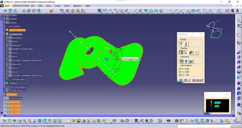
- Then click the fan cover. It will turn green or with green and red based on the draft angles.
- If the minimum draft angle is set to 3 and we have only 2 degrees of draft angle, it will show that portion in red. If the portion has enough draft angle, it will show it in green. Thus, the draft analysis is complete.
Output of draft analysis:
Screenshots of the Draft analysis report.