Wiring harness design in CATIA V5 - 3D modeling Week 4 Challenge
Aim:
Route the following harness layout in Electrical workbench. Make assumption for harness bundle diameters.
Objectives:
Add protective covering on all branches connected to DT06-2S & DT06-4S connectors. Keep end extremity at 30mm (from connectors end).
- DT06-4S
- DT06-6S
- DT06-2S
- DT06-08SA
Procedure :
DTO6-4S,6S,2S,08SA
These are Called as Automotive Housing & Connectors
These housings are designed for cable to cable connections. Their seals provide a robust seal with a high degree of environmental protection. Safe, versatile and reliable, DT plug connector housings are made from a thermoplastic which is ideal for automotive applications.You will not struggle for choice as the DT plugs are available in 2 to 12 pin options. They use size 16 DEUTSCH contacts, each with 13-amp continuous capacity. The housings feature an integrated latch for mating.
So We are Discussing In Deatail,
- DT06-4S
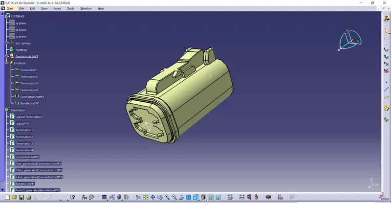
In the Above figure We Have Taken from TE resorce & Merged into Catia V5.
1.Then Selecting the Part design workbench & Taking A middle Point From The Connector Connecting Side As Well As Bundle Connecting Side based on no of terminals.
2.Taking the axis Origin of Connector connecting Point.
3.Adusting the y-axis is normal to the face of connector connectiong Point & X-axis would be locking side & Z-axis would be Up or down side.
4.Then go to the electrical part design & defining the bundle connection point As well as connector connection point with respect to their faces & Respresentations.
- DT06-6S
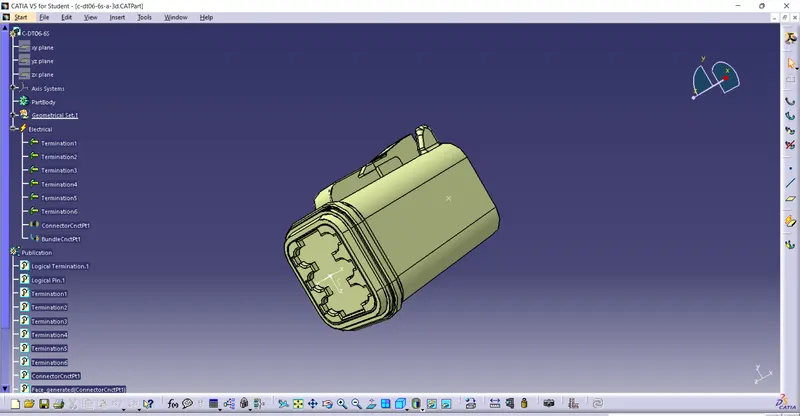
In the Above figure We Have Taken from TE resorce & Merged into Catia V5.
1.Then Selecting the Part design workbench & Taking A middle Point From The Connector Connecting Side As Well As Bundle Connecting Side based on no of terminals.
2.Taking the axis Origin of Connector connecting Point.
3.Adusting the y-axis is normal to the face of connector connectiong Point & X-axis would be locking side & Z-axis would be Up or down side.
4.Then go to the electrical part design & defining the bundle connection point As well as connector connection point with respect to their faces & Respresentations.
- DT06-2S
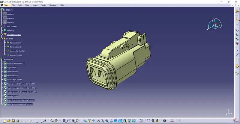
In the Above figure We Have Taken from TE resorce & Merged into Catia V5.
1.Then Selecting the Part design workbench & Taking A middle Point From The Connector Connecting Side As Well As Bundle Connecting Side based on no of terminals.
2.Taking the axis Origin of Connector connecting Point.
3.Adusting the y-axis is normal to the face of connector connectiong Point & X-axis would be locking side & Z-axis would be Up or down side.
4.Then go to the electrical part design & defining the bundle connection point As well as connector connection point with respect to their faces & Respresentations.
- DT06-08SA
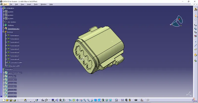
In the Above figure We Have Taken from TE resorce & Merged into Catia V5.
1.Then Selecting the Part design workbench & Taking A middle Point From The Connector Connecting Side As Well As Bundle Connecting Side based on no of terminals.
2.Taking the axis Origin of Connector connecting Point.
3.Adusting the y-axis is normal to the face of connector connectiong Point & X-axis would be locking side & Z-axis would be Up or down side.
4.Then go to the electrical part design & defining the bundle connection point As well as connector connection point with respect to their faces & Respresentations.
Proper Lign Alignment in Part Design:
After That We Go To the create A Line structure According to the given Question by using Catia By creating a New part on Sketch with given dimensions as shown in figure below.
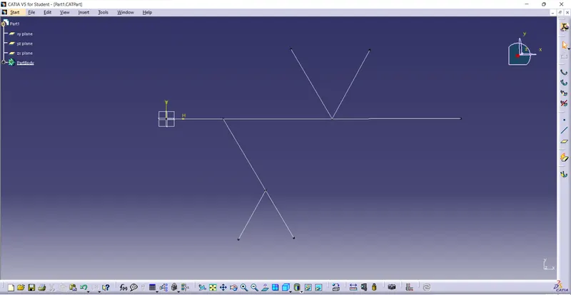
So that we have created the lines.
Mechanical Assembling :
no we have to Copy and paste the connectors,line part into the Assembly Workbench.
After that we have to manipulate the connectors according to the given figure then swap into their respective positions.
Electrical Harness Assembling :
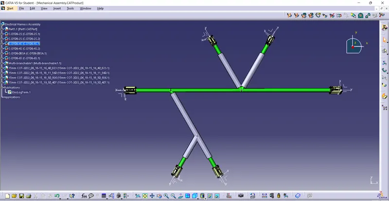
Then Go to the electrical harness Assembly Define the product as an geometric bundle.
Then go the multibranchable point Route the bundles And suiatable break points with respect to the given Diagram.
Then add protective coverings Keep & Extreme at 30mm From DT06-2S&4S Connectors end.
As Shown in Figure Below.
Conclusion :
Sucessfully Routed the following harness layout in Electrical workbench.