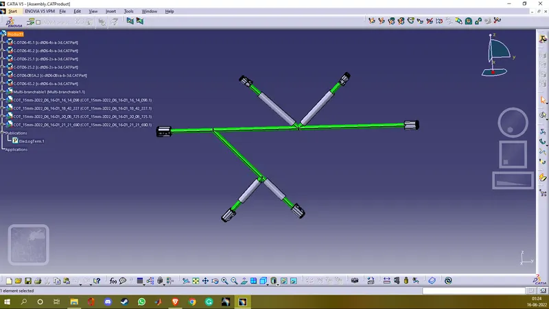
Wiring harness design in CATIA V5 - 3D modeling Week 4 Challenge
% Routing the following harness layout in the Electrical workbench using the following connectors DT06-2S, DT06-4S, DT06-6S and DT06-08SA. And adding protective covering on all branches connected to DT06-2S and DT06-4S connectors.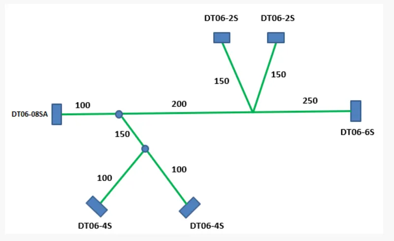
% Downloading and defining the connectors
- First we download the four connectors shown in the layout from www.te.com. Then we extract each connector and open them in CATIA V5 one by one.
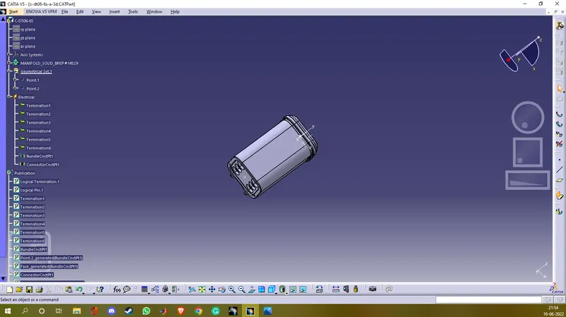
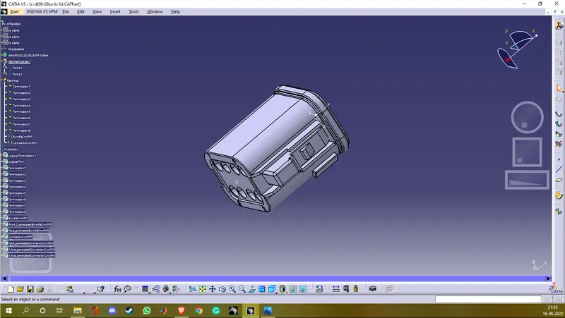
- Next we define the connectors geometrically in part design by making one point at the centre of the bundle entry side's face and making an axis at the centre of the connector connection side's face. Axis orientation should be as follows x-axis should point towards the locks on the connector, the y-axis should be normal to the surface and the z-axis should either point up or down.
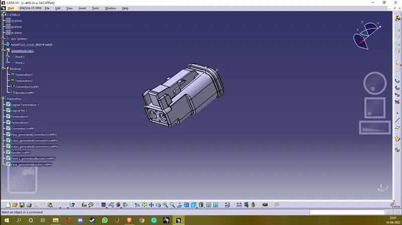
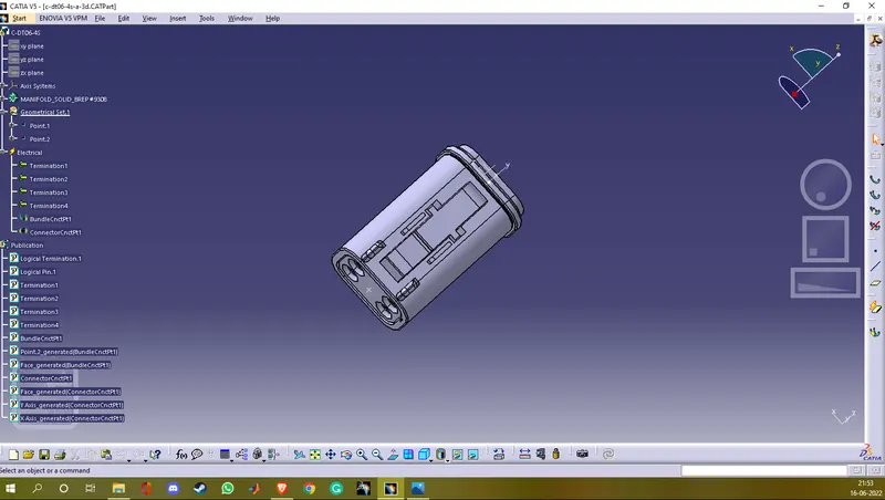
- Next we define the connectors electrically in the electrical part design. First, we click on define connector and select the respective connector and write a number of terminations according to the connector. Next, we define the bundle connection point by selecting the point on the bundle entry side and define the connector connection point by selecting the axis.
- The process is the same for all the connectors except there are changes in the no of terminals of every connector. DT06-2S has 2, DT06-4S has 4, DT06-6S has 6 and DT06-08SA has 8.
% Screenshots
* DT06-2S
* DT06-4S
* DT06-6S
* DT06-08SA
% Creating a catalogue
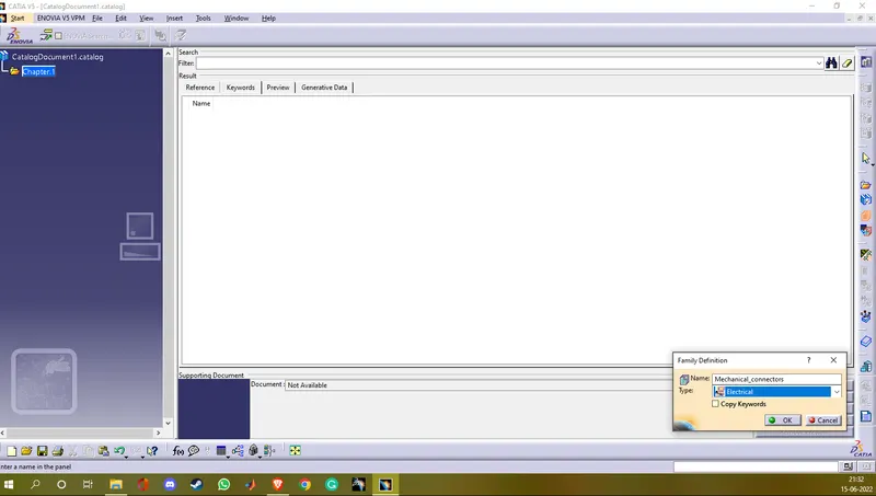
- First we create a catalogue by clicking on file>New part>Catalogue document.
- While creating a catalogue we named family as Mechanical_connectors and selected type as electrical and saved it.
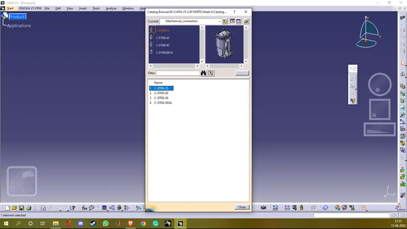
- Next we added all the electrically defined connectors in the catalogue.
% Screenshots
% Arranging the connectors as shown in the layout
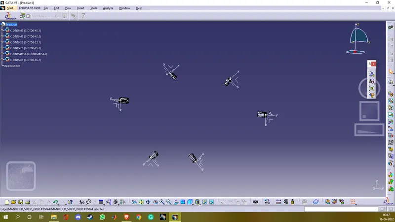
- We arranged the connectors in the assembly design workbench. First, we added the required connectors to the assembly design workbench.
- Next using the compass manipulation and snap we arranged the connectors as shown in the layout.
% Screenshots
% Creating bundle segments
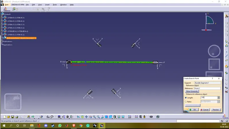
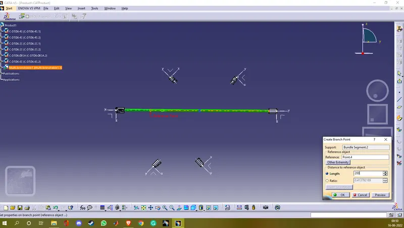
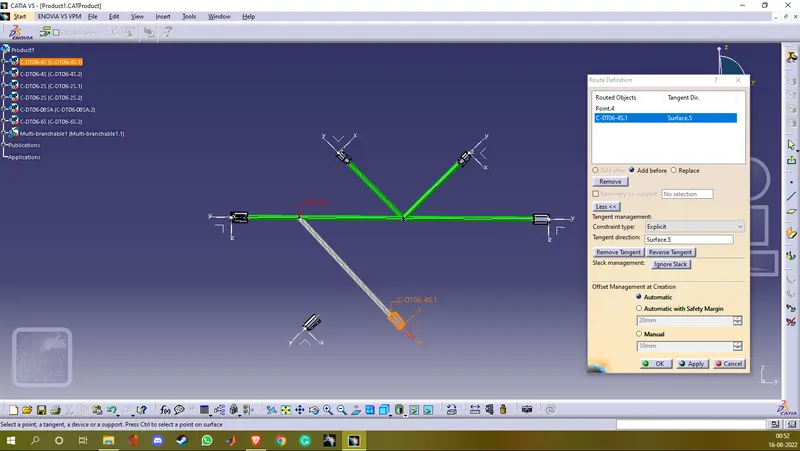
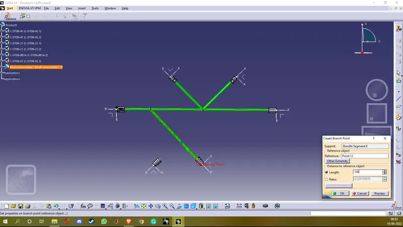
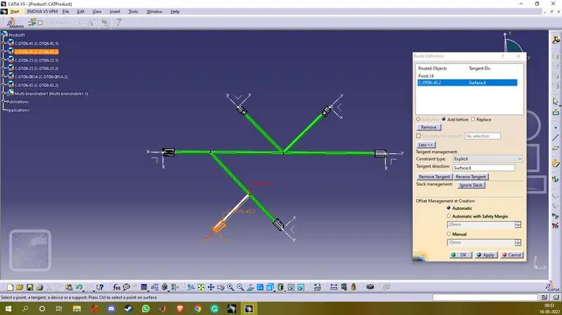
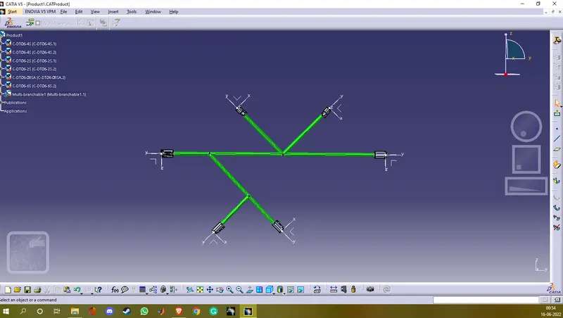
- Now we switch to electrical harness assembly workbench to create routings and branchable points.
- First we have to define the mechanical product as an electrical product to create bundle routings so we use the geometric bundle command and then select the product name on the tree structure.
- Now we can route the bundles and create branch points as we need.
% Screenshots
% Applying a protective coating
- We need to add a protective covering on all branches connected to DT06-2S AND DT06-4S and keep the covering 30mm open from the connector side.
- We use add protective covering command in the same workbench i.e wiring harness assembly workbench.
- We used a 15mm cot tube on a 10mm wire which we created previously.