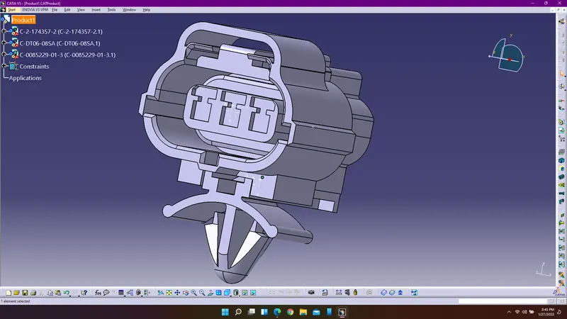
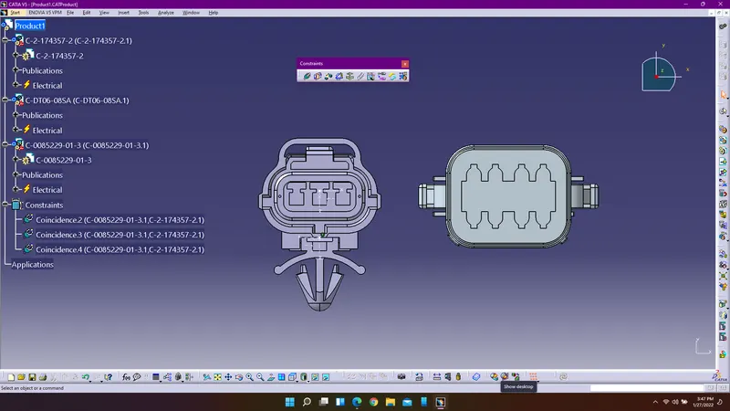
Wiring harness design in CATIA V5 - 3D modeling Week 2 Challlenge
Aim: To define the electric parameters for the given connectors and connector clip or cavity.
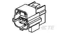
Connector: Connector is a electro-mechanical device which allows to join electrical conductors to create an electric circuit. Connectors are widely used in truck, Bus, Off-highway, Construction, Agriculture, Mining, Emergency Vehicles, Forestry, Recreational Marine, Motorcycle. These are automotive electromechanical components which are protected by the coverings of plastic.
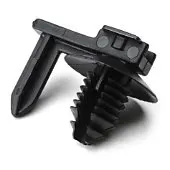
Connector Clip or Cavity: Cavity helps in providing secured positioning of connector over the surface. They are first mated with a connector on a wire harness or cable assembly, then secured to a surface using the integrated mount. With so many configurations available, attachment surfaces can be a hole, edge, stud or even another harness assembly.
Procedure to create the catologue:
1. Enter into catia V5R21 and select file menu and select new, then click catalogue document to create a new catalogue.
2. Select add family to create a family for connectors which includes all the connectors and define the type of the family as electrical.
3. Select the connectors to add them into the connectors family to access the connectors.
Procedure to define the electrical parameters for connectors:
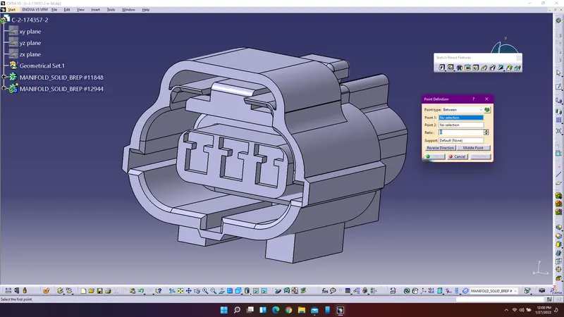
1. Open catia V5R21 and import the connectors and enter into the part design workbench to create a point the connector where the connector to connector connection will be happening.
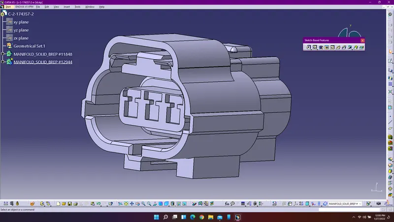
2. Insert an axis system by selecting the point as the origin and make sure to allign the axis accordingly.
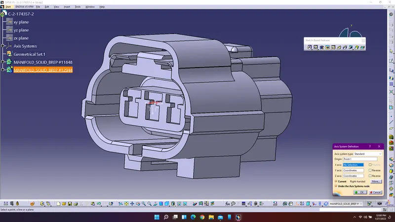
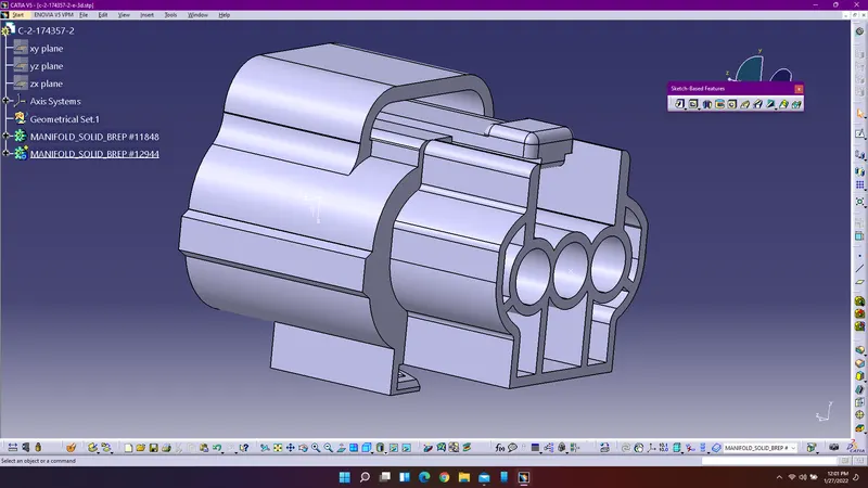
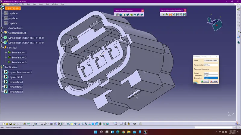
3. Create the point for bundle connection as well as for the cavity connection and insert an axis system for the cavity connection and arrange the axis accordingly.
4. Enter into the electrical part design workbench and using define connector command to define the given connector and enter the number of terminals for the given connector.
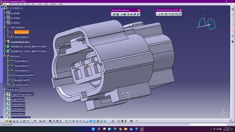
Axis system1 shows the connector connection point
5. Select the define connection connector point command to define the connector connection.
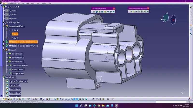
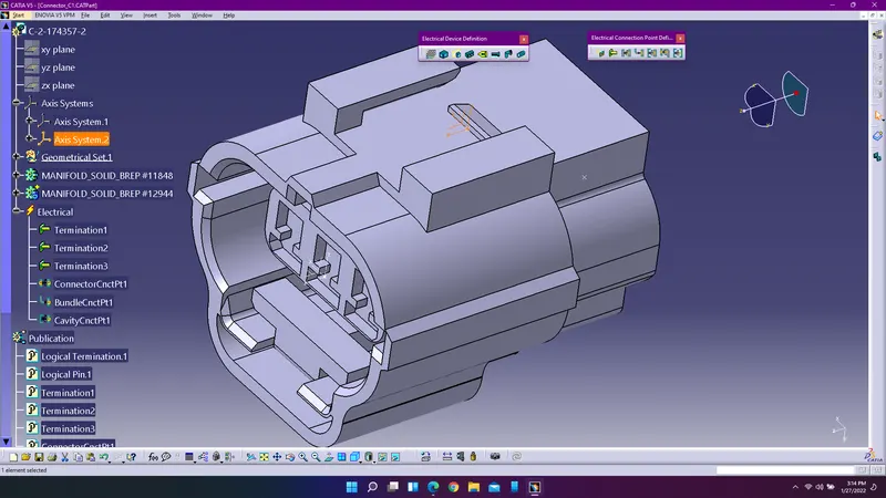
6. Similarly select the bundle connection point and cavity connection point to define the bundle connection and cavity connection.
Follow the same procedure to define the electrical parameters for the other connector.
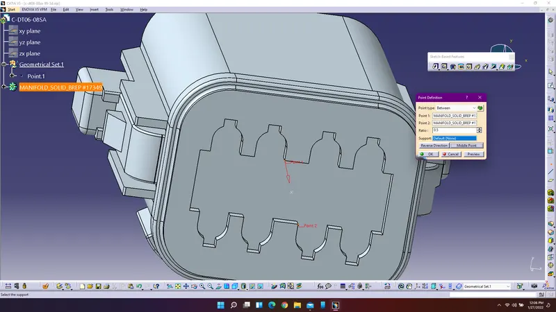
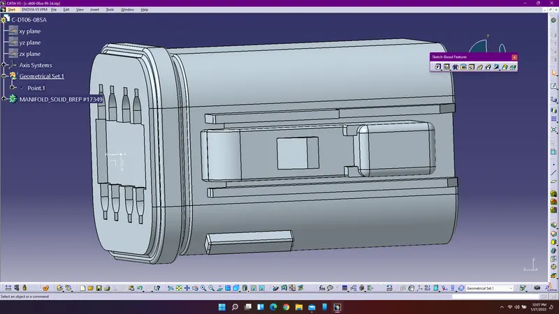
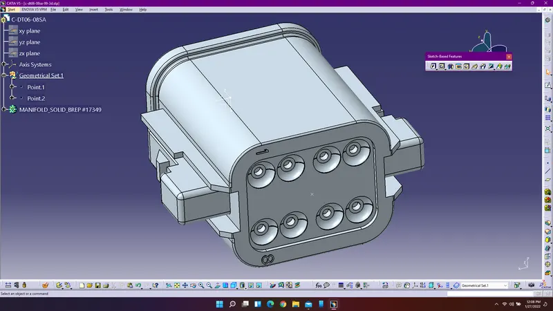
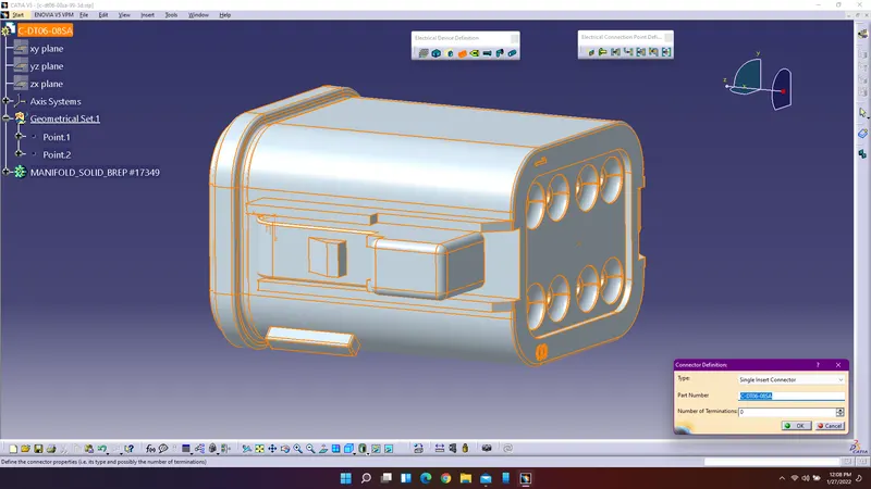
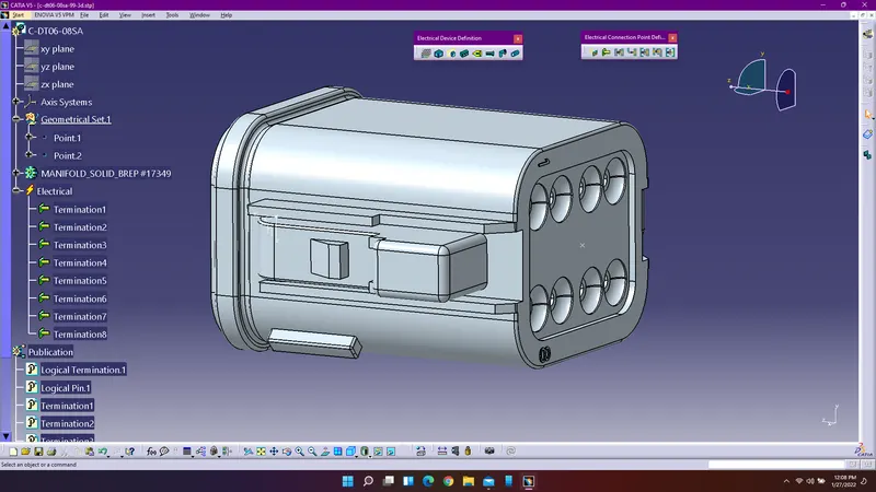
For cavity create a point on the appropriate position where the connector and clip is going to mate. Create an axis system at the point and enter into electrical part design workbench.
select define equipment to define the cavity and use define cavity command for defining the cavity component electrically.
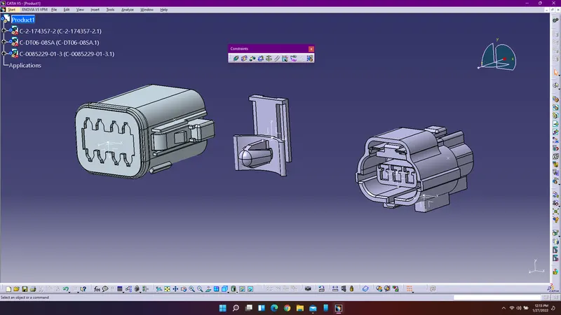
Enter into the electrical assembly design workbench to create the assembly for the connector and cavity.
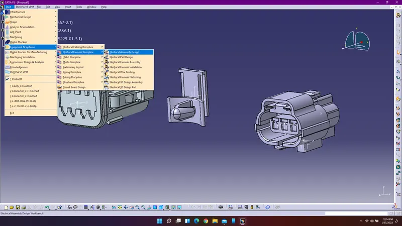
Establish the connection between connector and cavity using connect electrical devices command.