Wiring harness design in CATIA V5 - 3D modeling Week 2 Challenge
Step-by-Step Procedure
1. Launch CATIA V5
- Open CATIA V5 software.
2. Open the Electrical Part Design Workbench
- Go to `Start > Equipment & Systems > Electrical Part Design`.
3. Create or Open the Connector Part
- If you already have a connector part model, open it. Otherwise, create a new part and design the 3D geometry of the connector using the mechanical part design module.
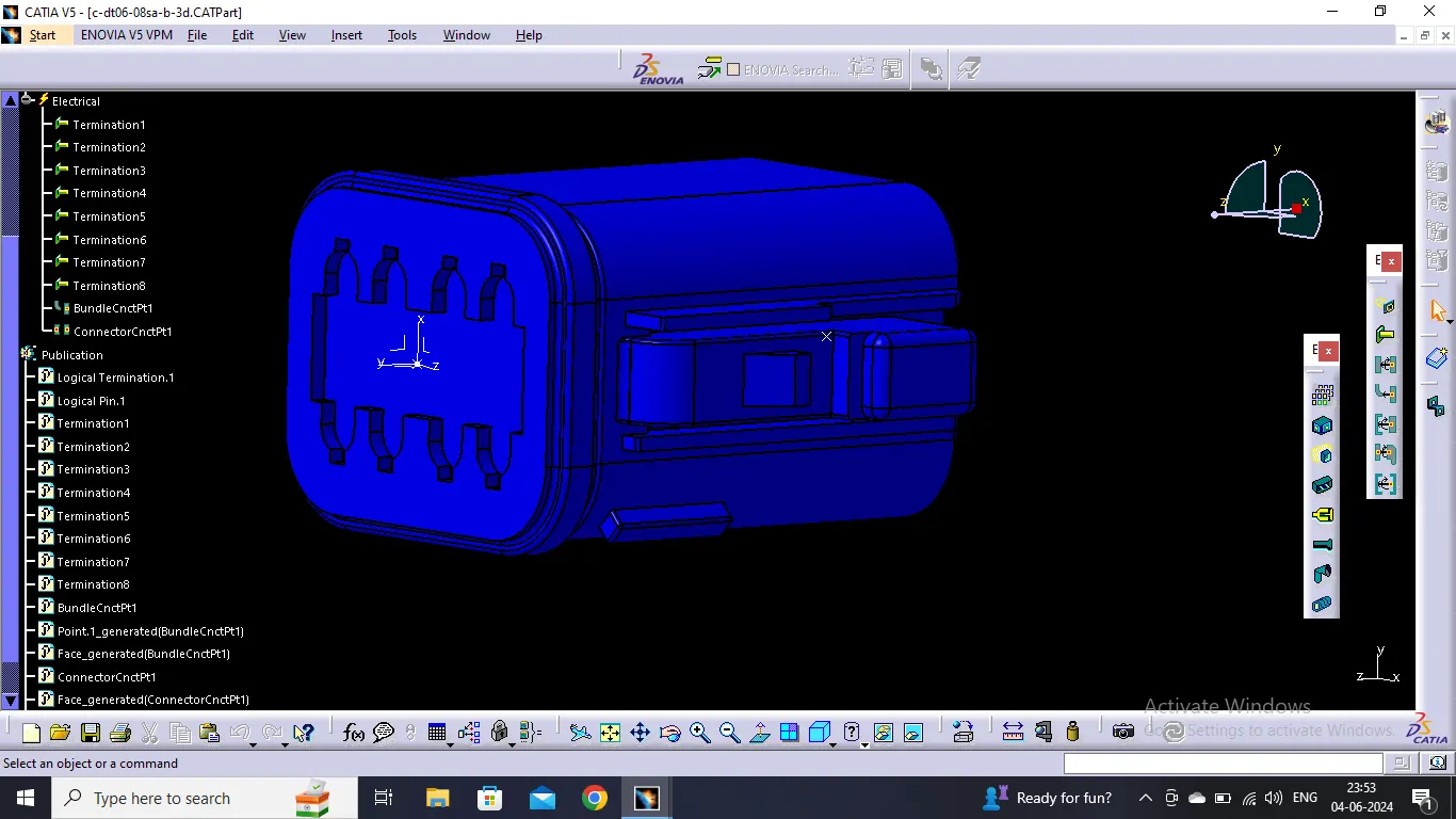
- In my case I have downloaded the STEP file te.com and I converted that step file in CAT part file later.
4. Define Connector as an Electrical Part
- With the part model open, switch to the `Electrical Part Design` workbench.
- Select `Define Connector` from the toolbar or `Insert > Electrical Part Design > Connector`.
5. Assign Connector Properties
- A dialog box will appear. Fill in the properties such as Part Number, Description, etc.
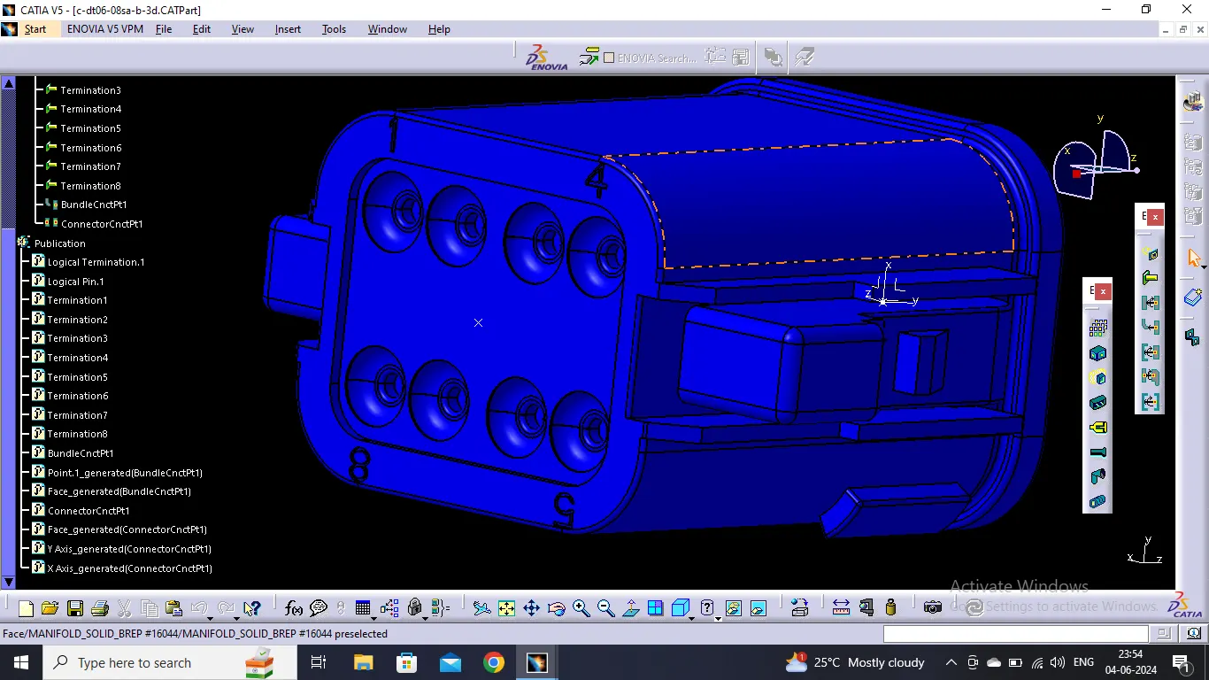
- Provide the number of terminals after inspecting the maximum possible terminations in connector.
6. Define Axis System and Bundle contact point
- Create a possible point to define to define the bundle connection point later.
- Create a possible axis system on the mating side of connector.
7. Add Electrical Connector Connection Point
- Select `Connector Connector Point ' option .
- Select the point and axis system to define the mating and orientation of connection.
8. Define Bundle Connection Points
- Select `Define Bundle Connection Point` option.
- Choose the location on the connector where the wire bundle will connect.
- Set the appropriate properties such as entry direction and diameter.
9. Save the Connector Part
- Save the part file after all definitions are completed.
Defining Clips
1. Open the Clip Part
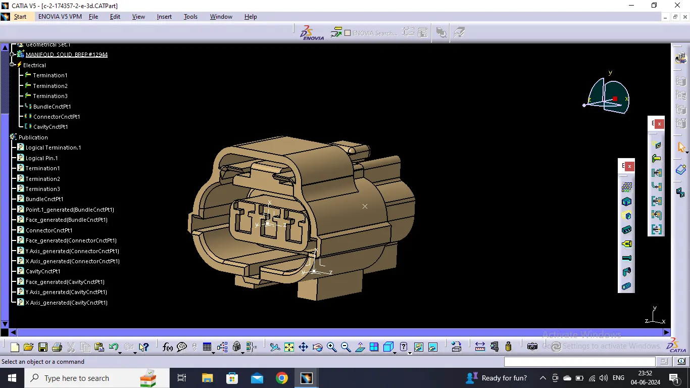
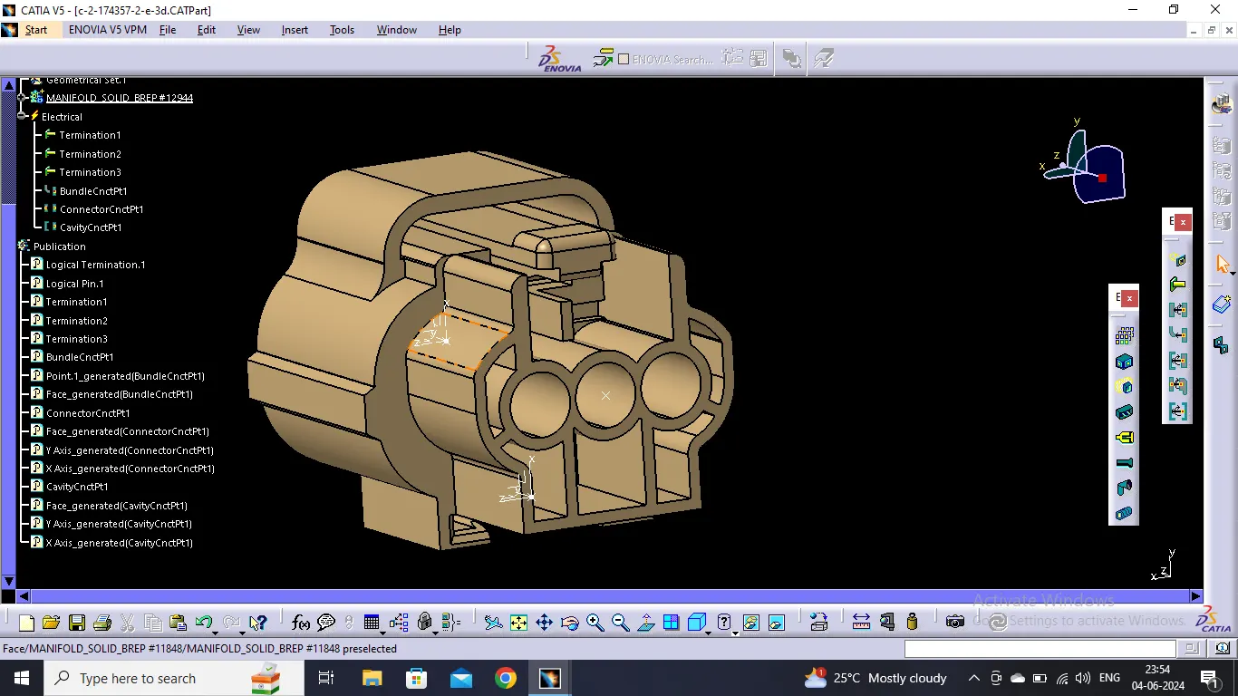
- Open or create the 3D model of the clip which will conform with your desired connector as cavity.
2. Define Clip as an Electrical Part
- With the part model open, switch to the `Electrical Part Design` workbench.
- Select `Define Mating part` option.
- Select the clip part an define it.
3. Assign Clip Properties
- Fill in the properties such as Part Number, Description, etc.
4. Define Axis System
- Create an Axis system at the mating junction of connector and clip .
5. Define the Cavity
- Select 'Cavity ' option.
- Define that by defining the axis system as per the connetor.
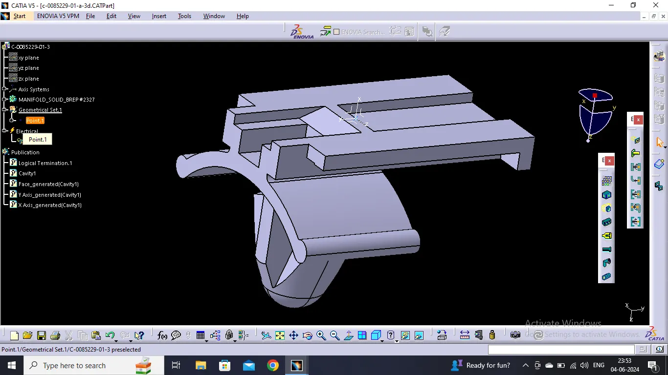
Integrating Connectors and Clips into the Electrical Assembly
1. Switch to Electrical Assembly
- Go to `Start > Equipment & Systems > Electrical Assembly`.
2. Create a New Product for Assembly
- Create a new product and save it as the electrical assembly.
3. Insert Connectors and Clips
- Use copy and paste the component in the product file from the active windows to add your defined connector and clip parts into the assembly.
4. Connect both Connector and Cavity
- Select 'Connect Electrical Components' option.
- Click both the connector and clip one by one , it will fix automatically if your axis system is accurate and correct .
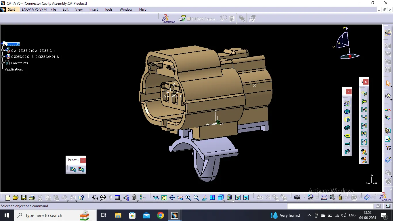
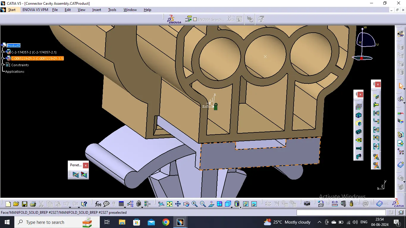
Created CATIA Catalogues to save the connectors and clips for later use.
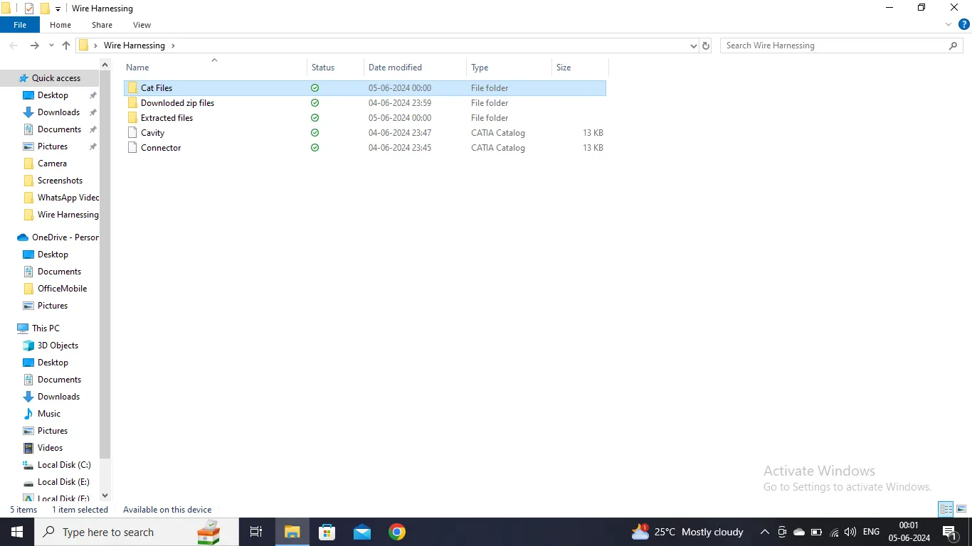
For verifying above documents , please refer to the zip file attached below with cat part, product , catalogue file and screenshots,