Wiring harness design in CATIA V5 - 3D modeling Week 2 Challenge
Objective:
Download following connectors & Connector clip cad data from given link & define it as Electrical Connector using Electrical Part design Workbench. Define all the necessary properties to Connectors & Clip.
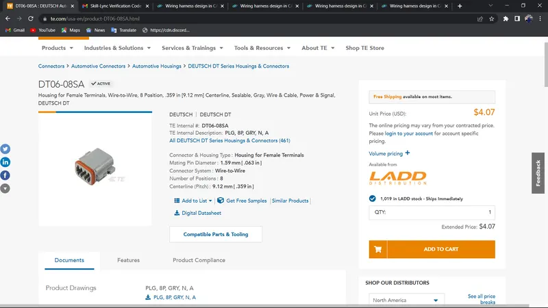
- Deutsch DT06 – 08SA ( https://www.te.com/usa-en/product-DT06-08SA.html)
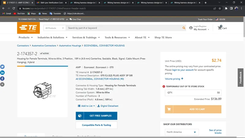
- Tyco 174357-2 (https://www.te.com/usa-en/product-2-174357-2.html?source=header-match)
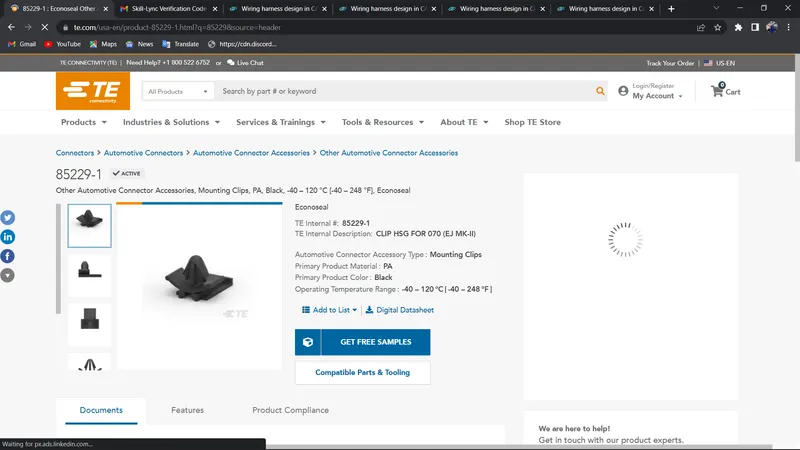
- Tyco 85229-1 – (https://www.te.com/usa-en/product-85229-1.html?q=85229&source=header)
STEPS WE HAVE TO FOLLOW:
WIRING HARNESS ASSEMBLY STRUCTURE
CONNECTOR DEFINITION
1.CREATE/DOWNLOAD CONNECTOR 3D
2.CREATE REQIURED GEOMETRICAL PARAMETER
3.DEFINE PART AS A CONNECTOR
4.DEFINE BUNDLE CONNECTOR
5.DEFINE CONNECTOR CONNECTION POINT
6.DEFINE CAVITY CONNETECTION POINT
Defining the connector
We need to define the connector by following the below steps.
- Download the connector data.
- Create required geometrical parameter.
- Define part as electrical connector.
- Define bundle connection point.
- Define connector connection point.
- Define cavity connection point.
Defining the mounting clip
- Download the clip 3d data.
- Create the geometry parameter.
- Define the part as mounting component.
- Define the part as cavity.
Defining the connector is described below
- Downloaded the cad data from the supplier's website and the images are shown below.
NOW FOLLOW THE STEPS FOR DEFINING ALL THE PART AS A ELECTRICAL COMPONENT”:
IMAGES ARE MENTIONED BELOW:
Tyco 174357-2
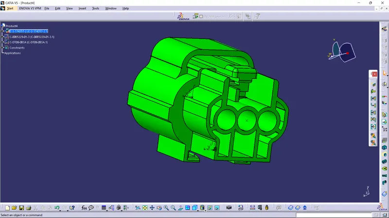
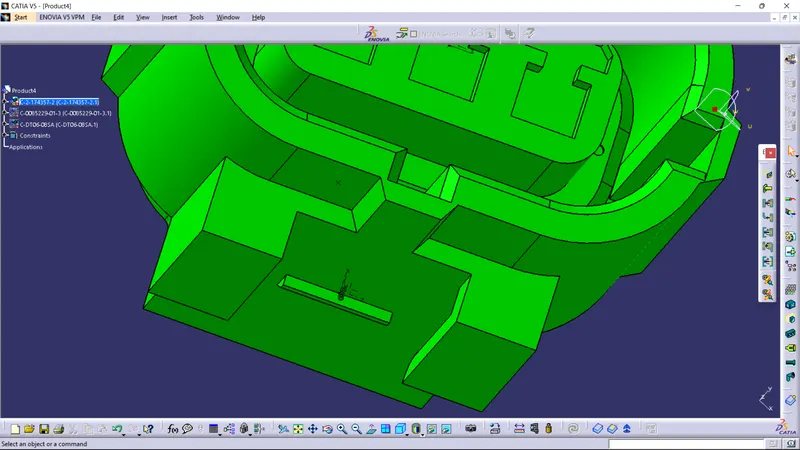
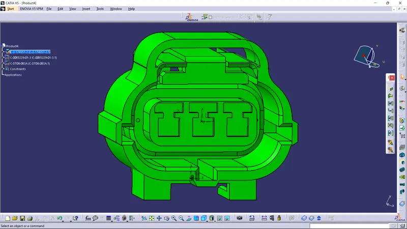
Deutsch DT06 – 08SA
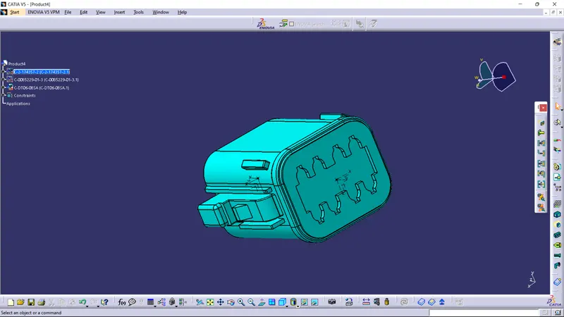
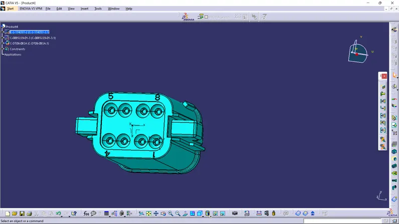
Tyco 85229-1
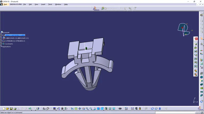
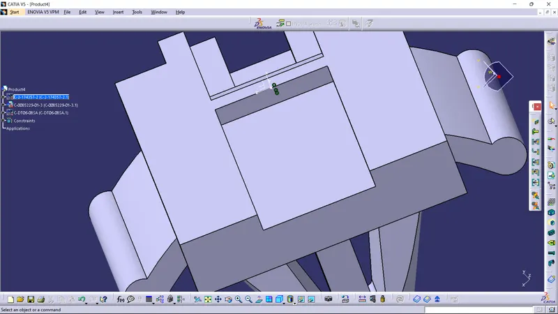
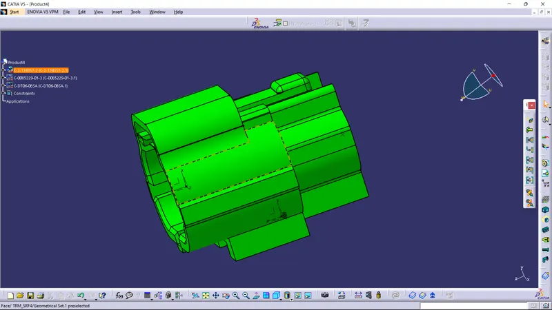
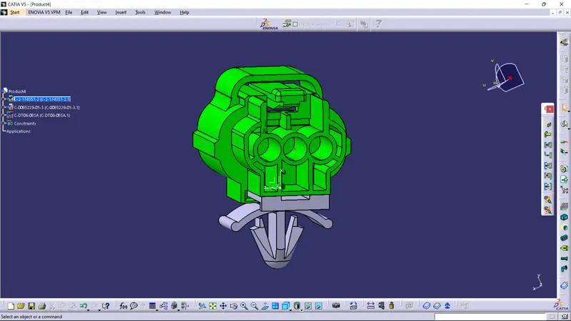
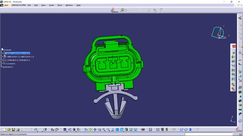
ASSEMBLY OF CONNECTOR AND CLIP:
THANKYOU......