Wiring harness design in CATIA V5 - 3D modeling Week 2 Challenge
{1} OBJECTIVE :-
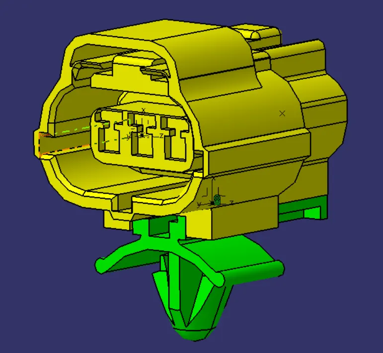
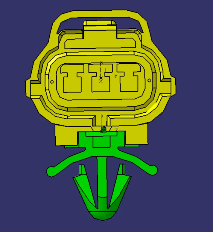
DOWNLOAD FOLLOWING CONNECTORS AND CONNECTOR CLIP CAD DATA FROM GIVEN LINK AND DEFINE IT AS ELECTRICAL CONNECTOR USING ELECTRICAL PART DESIGN WORKBENCH. DEFINE ALL THE NECESSARY PROPERTIES TO CONNECTORS AND CLIP.
- Deutsch DT06 – 08SA ( https://www.te.com/usa-en/product-DT06-08SA.html)
- Tyco 174357-2 (https://www.te.com/usa-en/product-2-174357-2.html?source=header-match)
- Tyco 85229-1 – (https://www.te.com/usa-en/product-85229-1.html?q=85229&source=header)
- {2} INTRODUCTION TO WIRING HARNESSES :-
(A) ELECTRICAL DISTRIBUTION SYSTEM IN AN AUTOMOTIVE INDUSTRIES :-
Automotive electrical distribution systems are embedded devices offered by automotive manufacturers that distribute the electricity generated from the transmission system (powerhouse) to individual components. Automotive vehicles have undergone many technological changes in a short period of time.
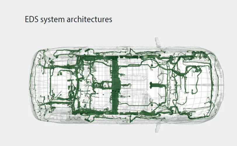
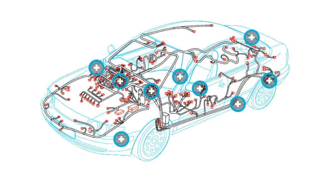
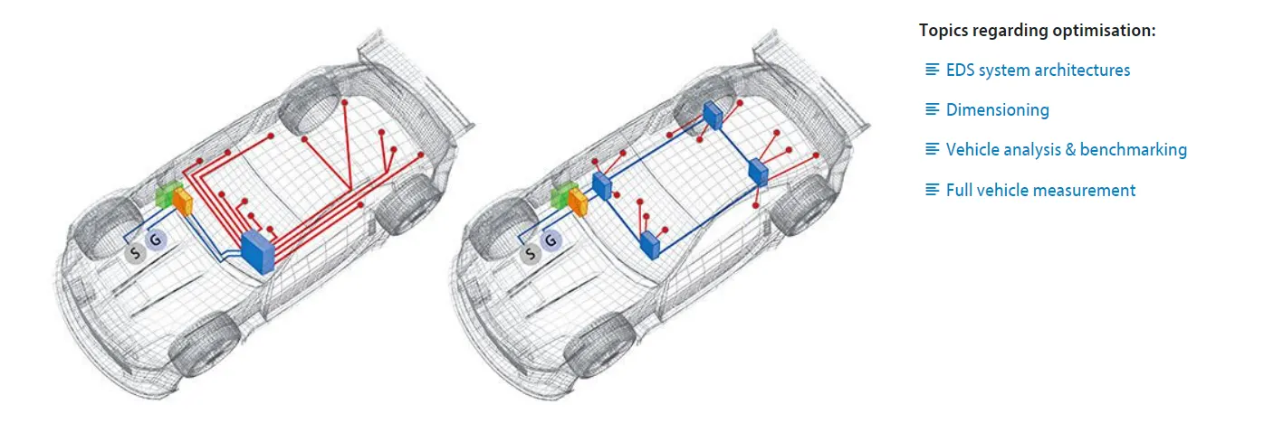
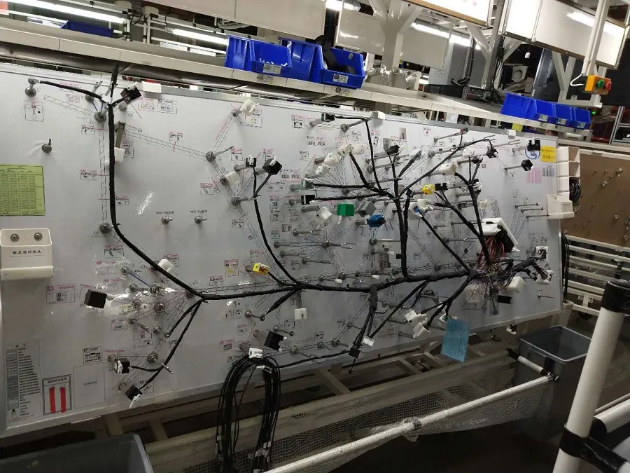
(B) A power distribution module (PDM) is used to provide electrical power from a main power source to a variety of vehicle or equipment peripherals which may require the following: Compact form factors when reliability and safety are factors. Cost reduction challenges. High power electrical terminals.
POwer Distribution Modules (PDM) for vehicles or commercial equipment feature multiple electrical power outputs, acceptance of many fuses, fuse types & relays and allow for custom configuration
(C) E AND E ARCHITECTUR :-
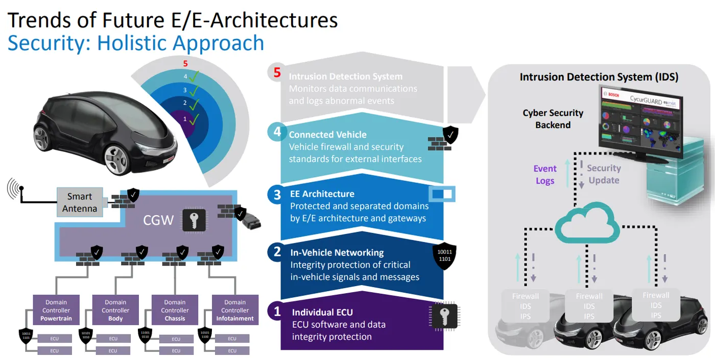
The term “electrical/electronic architecture” refers to the convergence of electronics hardware, network communications, software applications and wiring into one integrated system that controls an ever-increasing number of vehicle functions in the areas of vehicle control, body and security, infotainment, active safety, and other comfort, convenience, and connectivity functionality.
The first integration of electrical and mechanical systems occurred in the late 1950s with the advent of basic cruise control. In the ’60s, there were audio and lighting enhancements; in the ’70s, new emissions controls spurred advances in E/E architecture; and by the ’90s, managing the complexity of the electrical/electronic architecture was becoming an issue for OEMs. In the early 2000s, data and communication protocols drove new product requirements, and in the past decade, OEMs have focused on features and regulations governing occupant safety, driver distraction and fuel economy, which have led to adoption of high-voltage powertrains and systems.
Looking toward the future, E/E architectures will have to accommodate advances in automated driving, expanded infotainment, 5G connectivity and, most importantly, increased vehicle electrification. The traditional approach of incrementally adding new electronic control units (ECUs) with their own power, processing, data and connectivity for each new function no longer works; it will not scale to accommodate all of the new requirements for computing power, data processing and power distribution.
At the same time, OEMs are trying to automate the assembly of the wiring harnesses that serve as the backbone of the E/E architecture and have now become one of the most complex and unwieldy components of the vehicle.
The rise of all-electric vehicles is the tipping point that gives OEMs the opportunity to start fresh and create a new electrical/electronic architecture from the ground up — an architecture that considers the power and data needs of every electrical device in the vehicle and meets those needs in the most streamlined and integrated way possible.
The potential benefits and opportunities are impressive. OEMs that get it right will have a competitive advantage in delivering a better digital user experience.
(D) ELECTRICAL SCHEMATICS :-
An electrical schematic is a logical representation of the physical connections and layout of an electric circuit. A well documented schematic outlines the functionality of an electric circuit and provides the basis for assembly and troubleshooting of a system. A schematic can contain few or many symbols and connections and is normally read from left to right, top to bottom.
(E) Wiring harness topology: It is strategy to divide the harness between different pieces to achieve the best manufacturability, serviceability and cost-effective design. Ex: engine harness, door harness, tail gate harness. Note: Wiring harness cannot be repaired. It is advised to replace the damaged wiring harness parts.
(F) POWER DISTRIBUTION SYSTEM :-
Power distribution is the controlled transport of energy via the Power Distribution System (PDS) from the sources to all kinds of loads in the vehicle.
The Power Distribution System is therefore an essential part of the vehicle E/E Architecture.
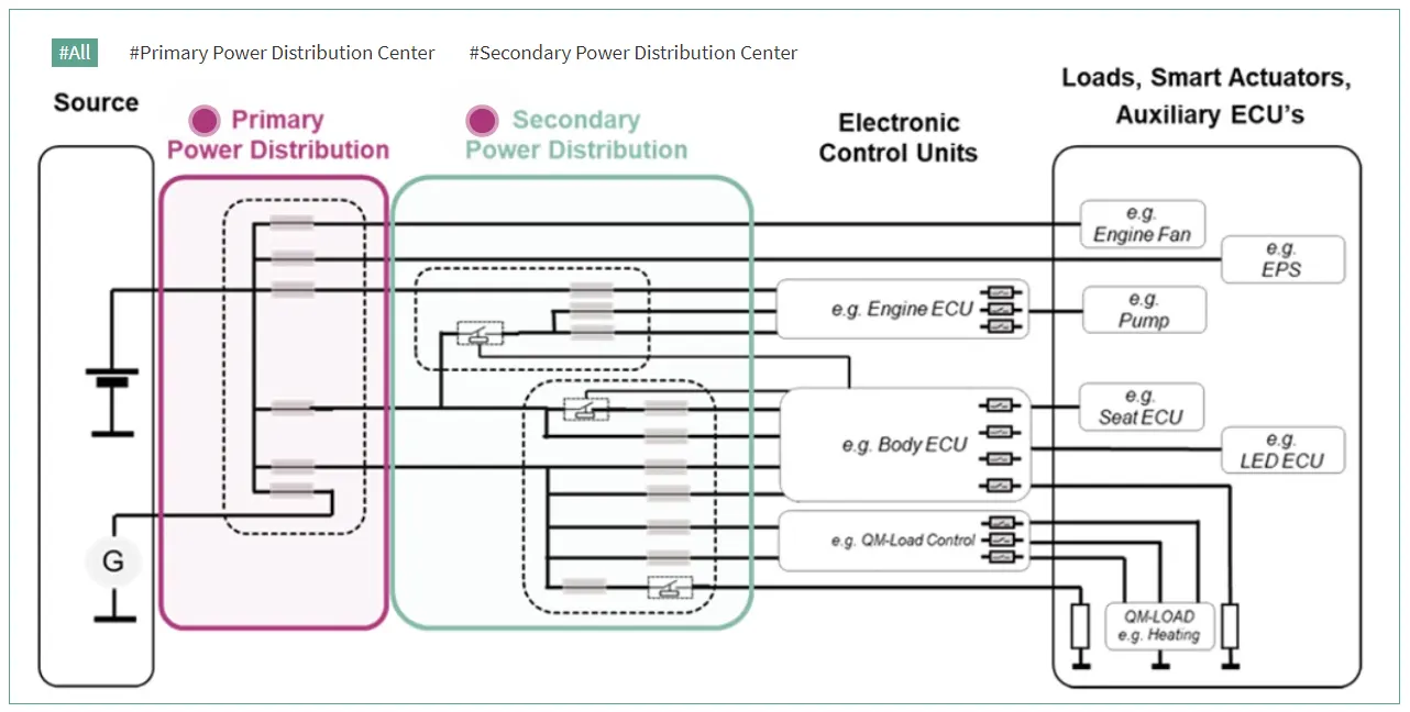
The Power Distribution System as it is today, is based on a wire harness to transport energy, fuses to protect the wire harness, relays / switches to start and stop the energy flow and ECUs to control the energy flow.
The Power Distribution System is built on three main elements - the primary power distribution,
the secondary power distribution and the Electronic Control Units (ECUs).
The primary power distribution is close to the source, often called the Pre-Fuse Box. The secondary power distribution as of today, is the classical Relay & Fuse Box which can be one central box or several distributed boxes.
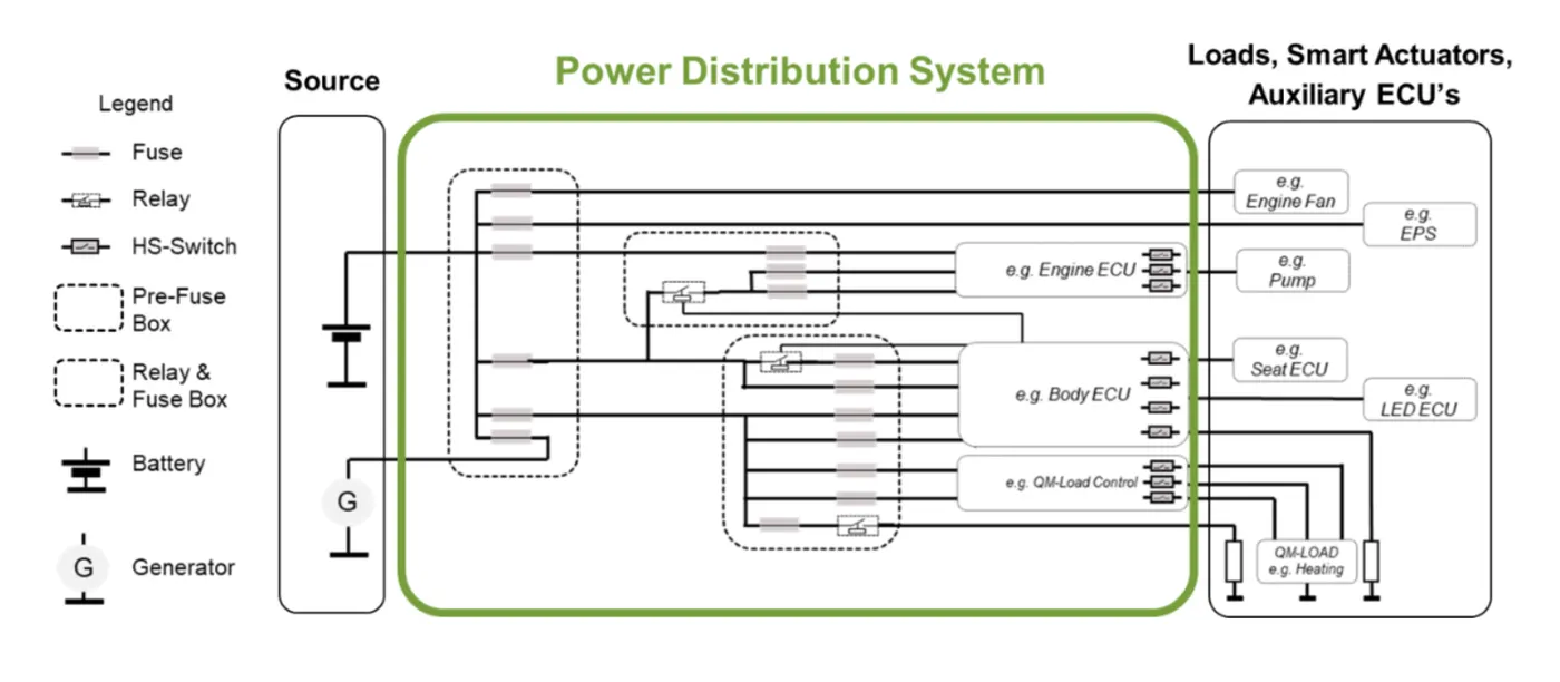
Today, designers are challenged to:
- harmonize the power distribution architecture with the In-Vehicle Network (IVN) architecture which is transforming to a zonal architecture with central computing
- introduce fail operational concepts for dependable power supply and distribution by the use of safety elements, mainly in the primary power distribution
- reduce wire harness complexity by decentralization and electrification of the secondary power distribution and the introduction of zone controller.
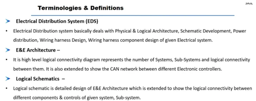
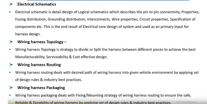
{3} TERMINOLOGIES AND DEFINATIONS :-
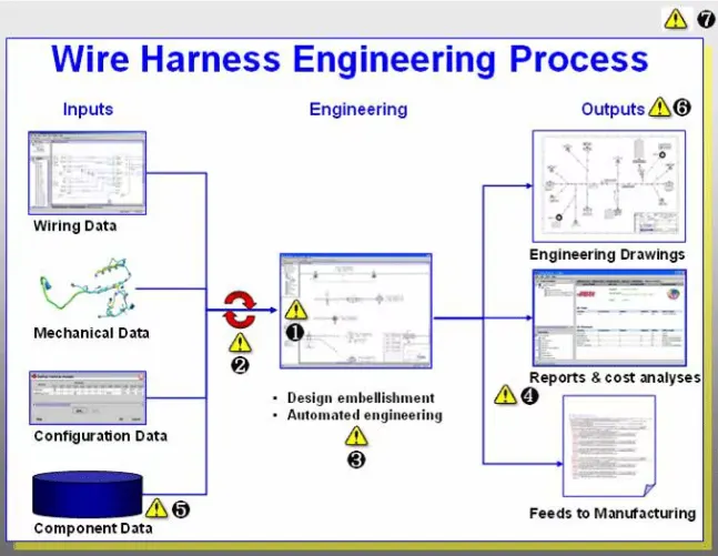
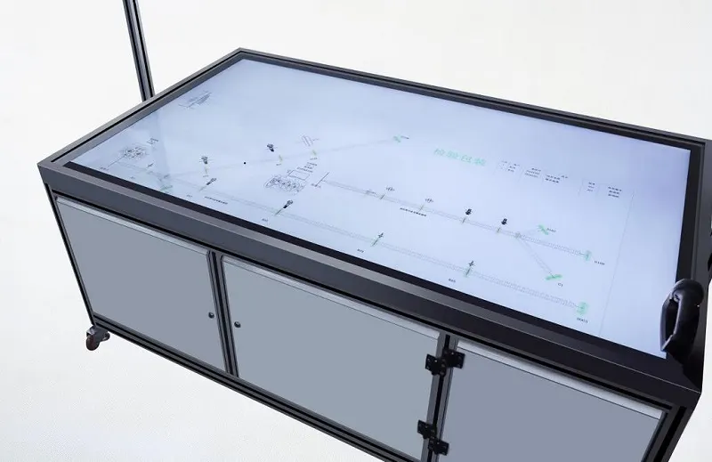
DEFINIG ELECTRIC PARAMETER FLOW CHART :-
WIRING HARNESS ASSEMBLY STRUCTURE - CONNECTOR DEFINATION :-
FOLLOWING PARAMETERS ARE REQUIRED TO DEFINE ANY CONNECTOR :-
GEOMETRY PARAMETRS :- POINTS AND CO-ORDINATE SYSTEM (AXIS)
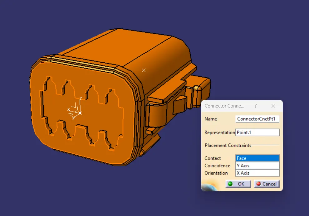
CONNECTOR CONNECTION POINTS :- THIS POINT IS USED FOR THE CONNECTION OF ONE CONNECTOR TO ANOTHER CONNECTOR.
HARNESS BUNDLE ENTRY POINTS :- THIS POINT DEFINS WHERE THE HARNESS BUNDLE SEGMENT POINT WILL END WHEN ROUTED TO THR ELECTRICAL CONNECTOR.
CAVITY CONNECTION POINT (OPTIONAL) :- THIS POINT IS USED TO DEFINE THE CONNECTION OF A CONNECTOR TO A CONNECTOR CLIP. THIS ONLY APPLIES TO CONNECTORS WHICH HAVE THE MOUNTING FEATURE FOR CONNECTOR CLIP.
{4} CONNECTOR DEFINATIONS IN CATIA V5 :-
(1) DEUTSCH DT06-08SA :-
CONNECTOR CONNECTION POINT :-
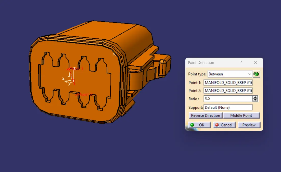
(A) CREATE MID POINT IN BETWEEN THE TWO POINTS OF CONTACT FACE WHICH WILL BE NORMAL TO THE WIRE BUNDLE INSERTION :-
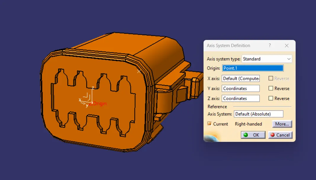
(B) CREATE AXIS SYSTEM WITH RESPECT TO THE POINT CREATED AND DEFINE THE Y AXIS OF AXIS SYSTEM POINTING TOWARDS THE FRONT FACE OF THE CONNECTOR , Z AXIS SHOULD BE POINTING ACROSS THE CONNECTOR FROM LEFT TO RIGHT , X AXIS SHOULD BE POINTING IN THE DIRECTION TOWARDS THE LOCKING MECHANISM OF THE CLIP.
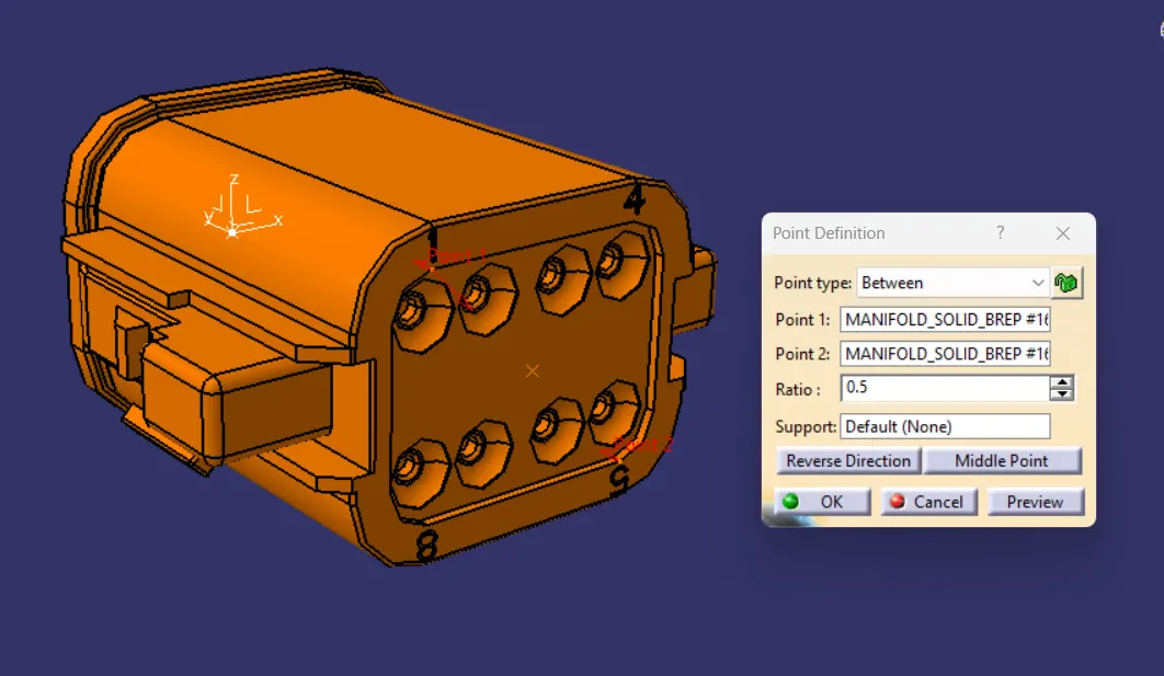
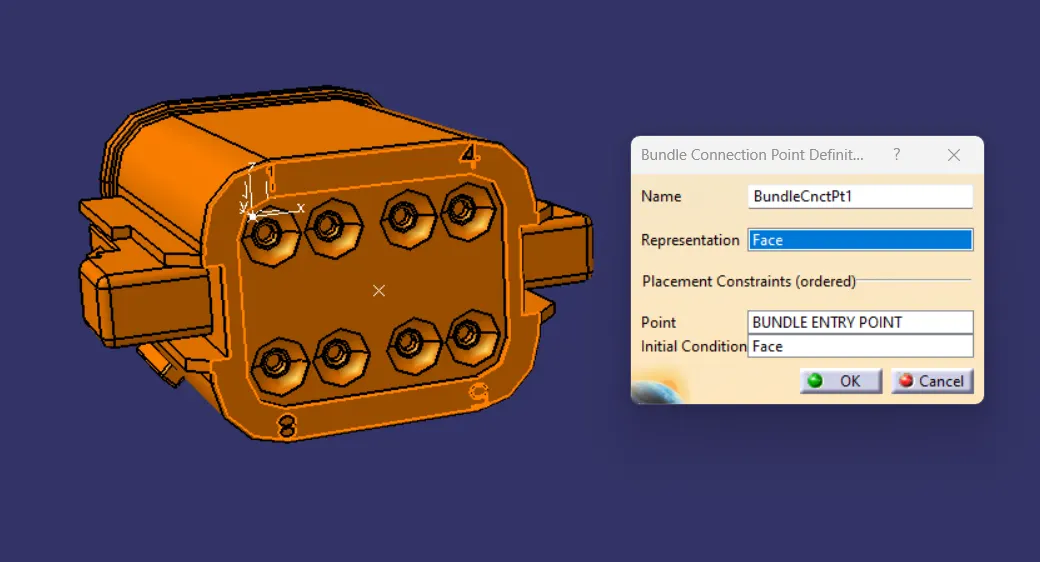
(C) BUNDLE CONNECTION POINT :-
CREATE MID POINT IN BETWEEN THE TWO END POINTS ON THE BACK FACE OF THE CONNECTOR WHICH WILL BE NORMAL TO THE BUNDLE INSERTION.
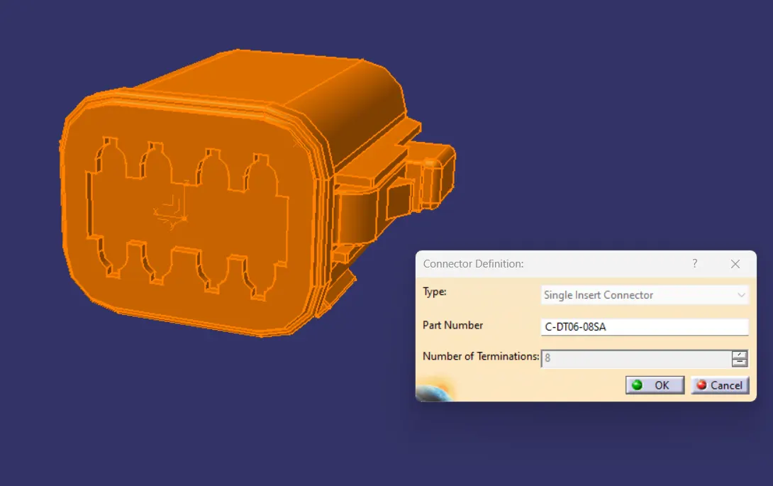
(D) SWITCH TO ELECTRICAL PART DESIGN.
DEFINE THE PART AS A CONNECTOR IN CATIA , THEN PROVIDE NO. OF TERMINATIONS AS 8 , BECAUSE THIS CONNECTOR CONSIST OF 8 ENTRY POINTS FOR WIRE.
(E) DEFINE BUNDLE CONNECTION POINT :-
(F) DEFINE CONNECTOR CONNECTION POINT :-
(2) TYCO 174357-2 :-
(A) CREATE MID POINT IN BETWEEN THE TWO POINTS OF CONTACT FACE WHICH WILL BE NORMAL TO THE WIRE BUNDLE INSERTION :-
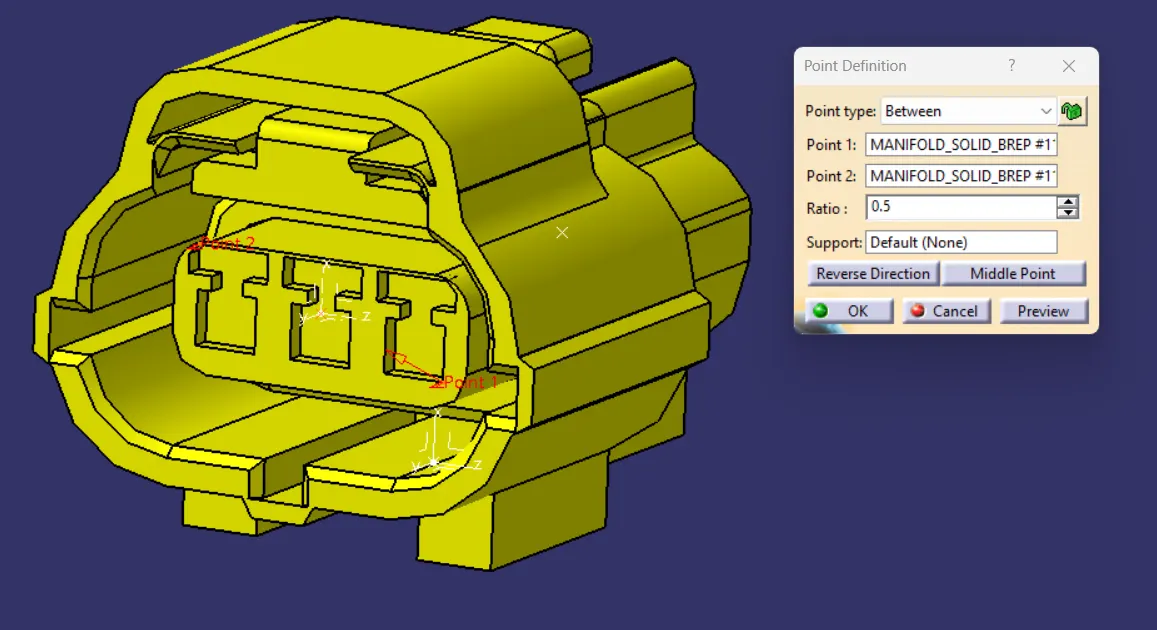
(B) CREATE AXIS SYSTEM WITH RESPECT TO THE POINT CREATED AND DEFINE THE Y AXIS OF AXIS SYSTEM POINTING TOWARDS THE FRONT FACE OF THE CONNECTOR , Z AXIS SHOULD BE POINTING ACROSS THE CONNECTOR FROM LEFT TO RIGHT , X AXIS SHOULD BE POINTING IN THE DIRECTION TOWARDS THE LOCKING MECHANISM OF THE CLIP.
(C) BUNDLE CONNECTION POINT :-
CREATE MID POINT ON THE BACK FACE USING THE MIDDLE CIRCLE OF THE CONNECTOR WHICH WILL BE NORMAL TO THE BUNDLE INSERTION.
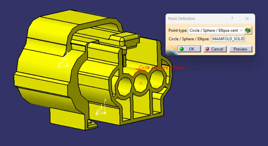
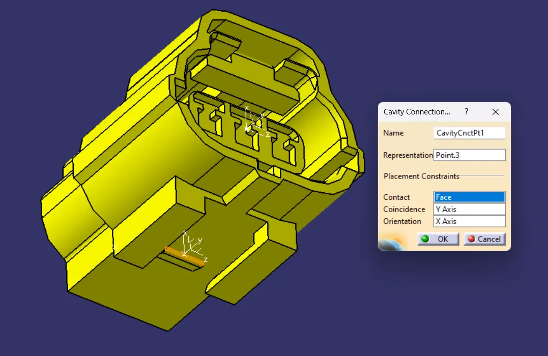
(D) CREATE CAVITY CONNECTION POINT ON THE MIDDLE POINT OF THE CURVE OR LINE LAYING ON THE CONTACT FACE OF THE CONNECTOR TO THE CAVITY.
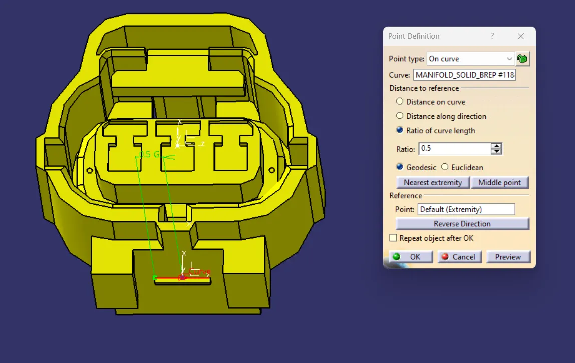
(E) CREATE CAVITY CONNECTION AXIS SYSTEM.
(F) SWITCH TO ELECTRICAL PART DESIGN.
DEFINE THE PART AS A CONNECTOR IN CATIA , THEN PROVIDE NO. OF TERMINATIONS AS 3 , BECAUSE THIS CONNECTOR CONSIST OF 3 ENTRY POINTS FOR WIRE.
- (G) DEFINE BUNDLE CONNECTION POINT.
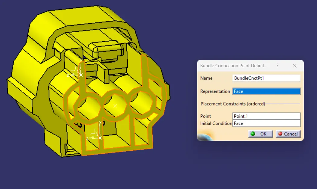
- (H) DEFINE CONNECTOR CONNECTION POINT.
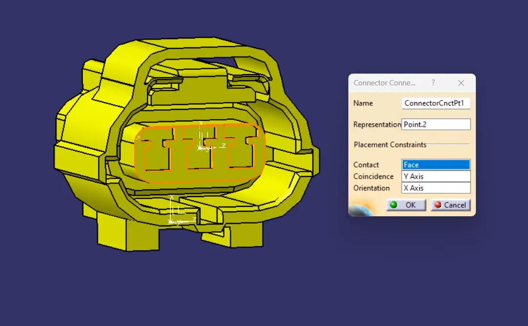
- (I) DEFINE CAVITY CONNECTION POINT.
(3) TYCO 85229-1 :-
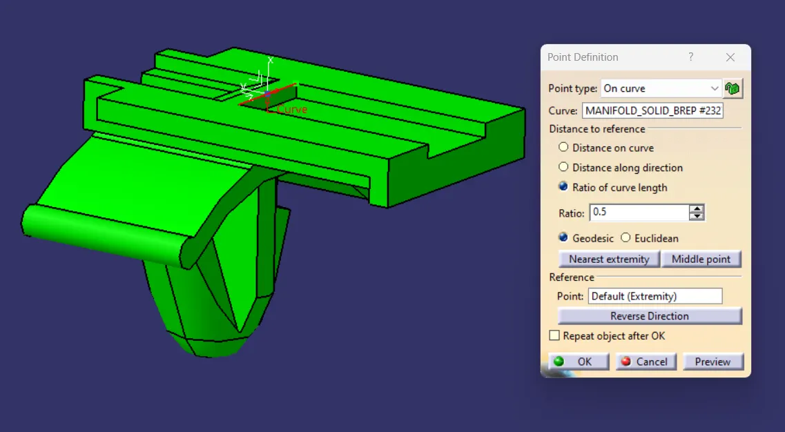
- (A) CREATE MID POINT USING THE UPPER LINE LAYING ON THE CONTACT SURFACE OF THE CAVITY.
- (B) CREATE CAVITY CONNECTION POINT.
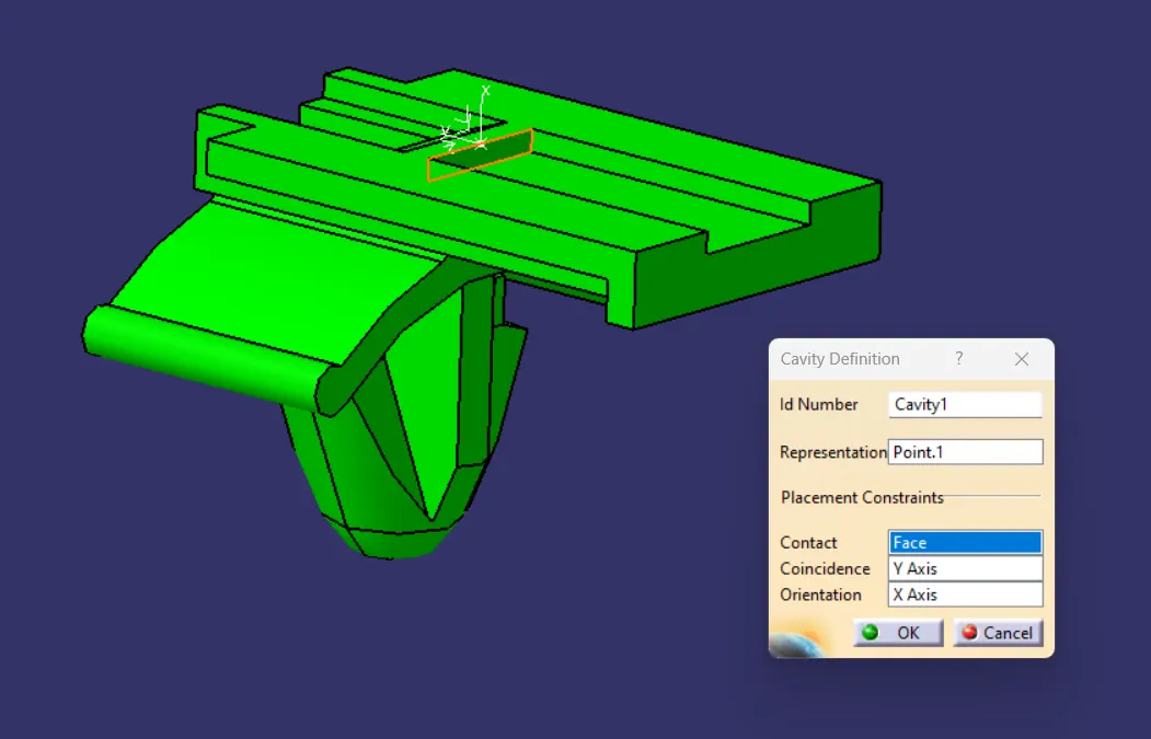
- (C) CREATE CAVITY CONNECTION AXIS SYSTEM AND ORIENT THE CAVITY CLIP AS THE SAME WAY AS CONNECTOR.
- (D) SWITCH TO ELECTRIC PART DESIGN AND DEFINE THE PART AS MOUNTING EQUIPMENT.
- (E) DEFINE CAVITY CONNECTION POINT.
{5} ELECTRICAL ASSEMBLY DESIGN :-
(A) CREATE ASSEMBLY IN ELECTRICAL ASSEMBLY DESIGN COPY BOTH THE CONNECTOR AND THE CAVITY CLIP PASTE IT TO THE ELECTRICAL ASSEMBLY.
(B) SELECT DEFINING ELECTRIC CONNECTION, USE CONNECT ELECTRICAL DEVICES COMMAND.
(C) SELECT CAVITY AND CONNECTOR.