Radar Mast & Final Assembly of Yacht
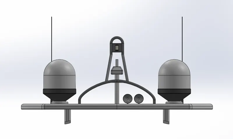
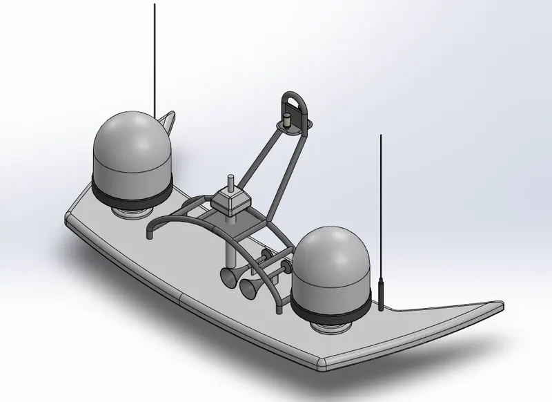
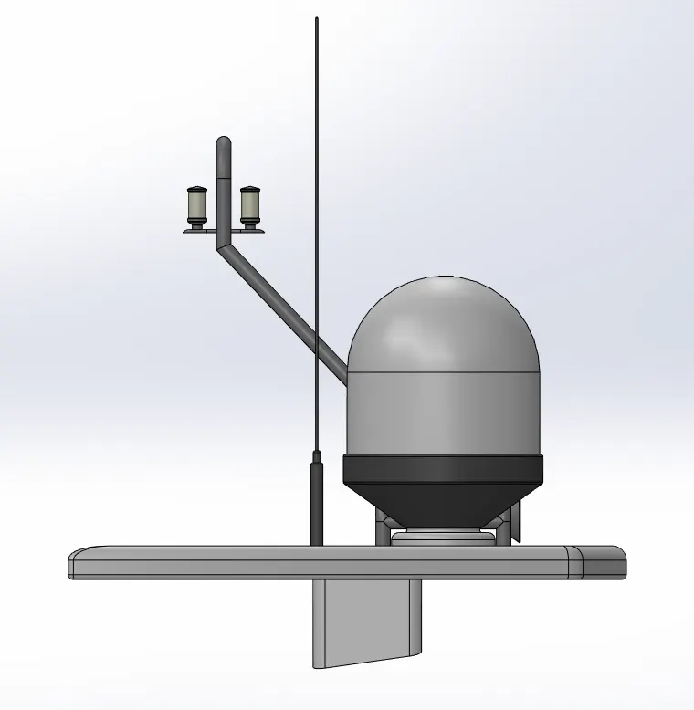
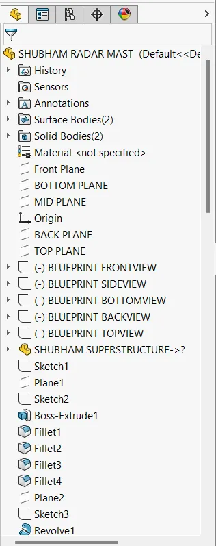
{ RADAR MAST } :-
A. FRONT VIEW:-
B. ISOMETRIC VIEW :-
C. SIDE VIEW :-
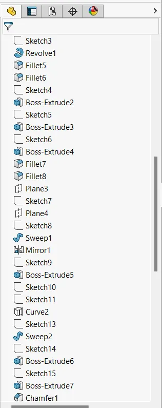
D. FEATURE TREE :- 1,2,3
{ YACHT ASSEMBLY } :-
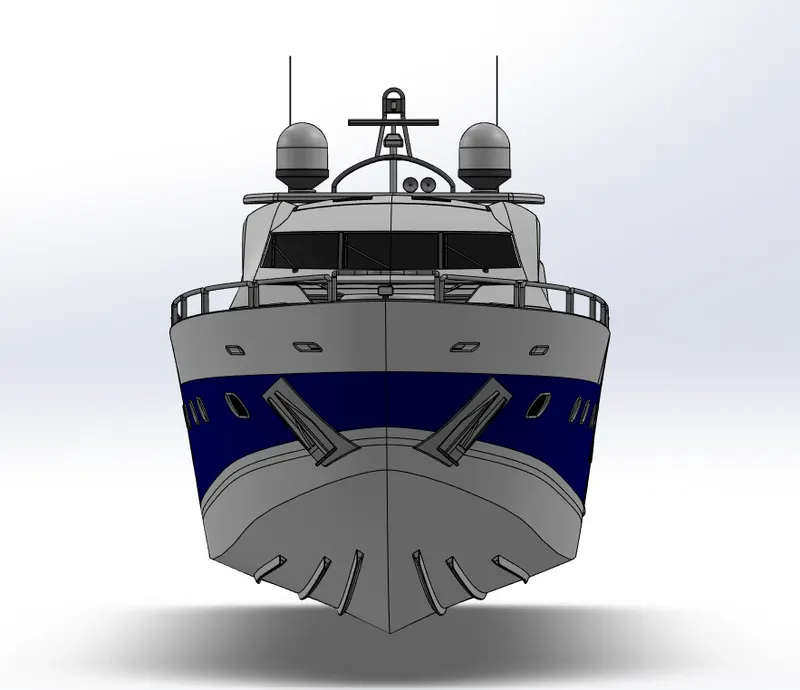
A. FRONT VIEW :-
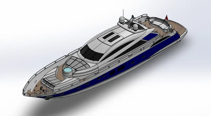
B. ISOMETRIC VIEW :-
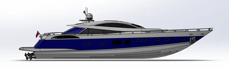
C. SIDE VIEW :-
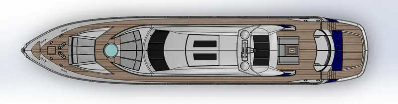
D. TOP VIEW :-
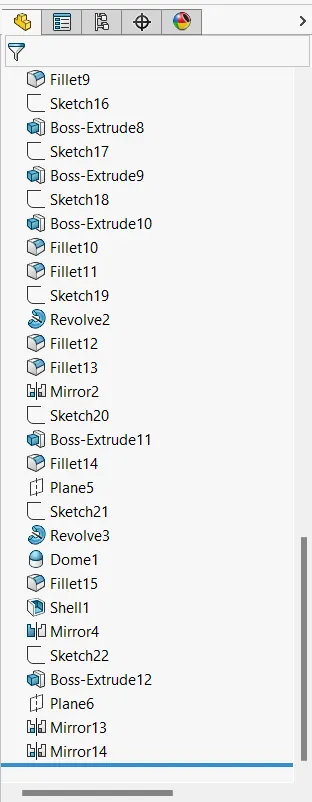
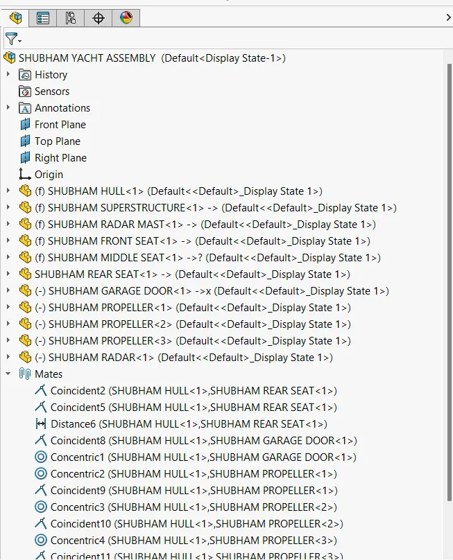
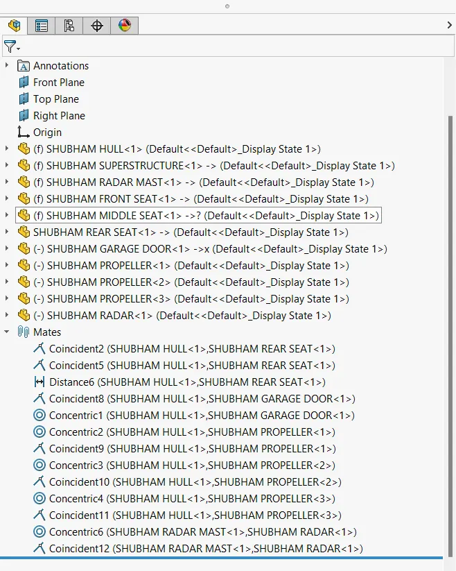
E. FEATURE TREE :- 1,2
REPORT ON SUNSEEKER YACHT MODEL USING SOLIDWORKS :-
1. TITLE :- DESIGNING OF ALL THE PARTS AND ASSEMBLY OF SUNSEEKER YACHT MODEL USING SOLIDWORKS SOFTWARE.
2. OBJECTIVE :- DISIGNING OF ALL THE PARTS AND ASSEMBLY OF SUNSEEKER YACHT MODEL USING VARIOUS COMMANDS AND FEATURES IN SOLIDWORKS.
3. INTRODUCTION :-
Sunseeker yacht is a travelling medium for human which includes all luxary and travel by means of waterways, A yacht is a sailing or power vessel used for pleasure, cruising, or racing. though the term generally applies to such vessels that have a cabin with amenities that accommodate overnight use. I used Solidworks to design sunseeker yacht. There are different modules in Solidworks which are used to design different component.
(1). Computer Aided Design (CAD)software like Solidworks is very simple to use for the creation of 3D solid model and can be created faster. The main advantage of Solidworks is that everyone can use it as compared to other cad software.
(2). Solidworks is mainly used in many industries for the design and assembly of there product due to which productivity increases and the cost is also less. With the equation tool in Solidworks it is easy to write all the global variables and
evaluate the dimension through global variables.
4.DESIGN METHODOLOGY/APPROACH :-
Different components of Sunseeker yacht are given below in table with their use:-
| Item No. | Part Name (Figure No.) | Use of Part |
| 1. | Propeller (Figure 1) | Transmit power |
| 2. | Radar (Figure 2) | Signals |
| 3. | Blueprint setup (Figure 3) | Base for modeling |
| 4. | Hull (Figure 4) | Water tight body |
| 5. | Front seats (Figure 5) | Rest |
| 6. | Middle seats (Figure 6) | Rest/dining |
| 7. | Rear seats (Figure 7) | Rest |
| 8. | Superstructure (Figure 8) | Controlling hub of yacht |
| 9. | Garage door ( Figure 9) | Moving door (opening/closing) for parking space |
| 10. | Radarmast (Figure 10) | Part used for proper alignment of radar and navigation system |
| 11. | Assembly of sunseeker yacht (Figure 11) | ALLIGNMENT of all parts of the model |
| 12. | Rendering of sunseeker yacht (Figure 12) | Rendered visuals of sunseeker yacht |
5. DESCRIPTION :-
In Solidworks, we use different module for different purpose. Here we use Sketch Module, Surface Module,
Features Module, Evaluate Module, Render Module, Solidworks Visualize Module, etc. for designing SUNSEEKER YACHT MODEL.
(1) Sketch Module :- In Sketch Module, we use Line Command, Rectangle Command, Circle Command, Arc Command,
Spline Command, Fillet Command, Chamfer Command, Point Command, Trim Entities, Convert Entities,
Offset Entities, Mirror Entities and Pattern Command.
(2) Surface Module :- In Surface Module, we use Extruded Surface Command, Revolved Surface Command, Swept Surface
Command, Lofted Surface Command, Boundary Surface Command, Filled Surface Command, Planar Surface Command, Offset Surface Command, Extend Surface Command, Trim Surface Command, Untrim Surface
Command, Knit Surface Command, Freeform Command, Thicken Command, Fillet Command, Chamfer
Command, Reference Geometry and Curves.
(3) Feature Module :- In Features Module, we use Extruded Command, Revolved Command, Swept Command, Lofted Command,Boundary Command, Extruded Cut Command, Revolved Cut Command, Swept Cut Command, Lofted Cut
Command, Boundary Cut Command, Hole Command, Fillet Command, Chamfer Command, Pattern Command,Dome Command, Draft Command, Shell Command,Mirror Command, Move Command, Reference Geometry, Curves, Split Command and Combine Command.
(4) Evaluate Module :- In Evaluate module of solidworks it is used for evaluation,simulation and flow simulation of the entire model.
(5) Render Module and SW Visualize Module :- This module in photoview 360 and solidworks visualize is used to properly render images of the model and also used for setting up the scene and the enviornments , camera setup,prespective vision and lights setup for better visuals of the model created in solidworks.
6. COMPONENTS OF SUNSEEKER YACHT :-
(1) PROPELLER :- A device that consists of a central hub with radiating blades placed and twisted so that each forms part of a helical surface and that is used to propel a vehicle (such as a ship or airplane).
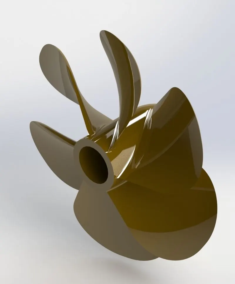
So, here the command and features used in the creation of propeller of sunseeker yacht model are :-
A. Line Command:- line command is solidwork is used to create line from one end point to other end point in different planes and in any direction. as shown in the sketch image.
B. Splines are used to draw complex curves. Solidworks supports two types of splines, B-splines and style splines. We can use B-splines to create complex curves. One can define and modify them using several controls including spline points, spline handles and control polygons.
C. Revolve Command :-Revolve command in solidwork is used to create a sketch that contains one or more profiles and a centerline, line, or edge to use as the axis around which the feature revolves.
D. Loft Command :- Loft command in solidworks creates a feature by making transitions between profiles. A loft can be a base, boss, cut, or surface. where we cn create a loft using two or more profiles.
E. Fillet Command :- Fillets command in solidwork is used to placed feature that round off or cap interior or exterior corners or features of a part. You can create: Edge fillets Based on selected edges.
F. Cut Extrude Command :- Extruded cut feature in solidwork is used to remove material from the part. The End Condition, Draft, and Thin Feature options are same as described in Extruded Boss/Base.
G. Circular Pattern Command :- Circular patterns command in solidwork is used to create multiple instances of one or more features that you can space uniformly around an axis. Pattern instances inherit the feature color of the original feature when the: Pattern is based on one feature.
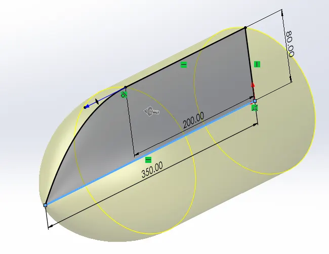
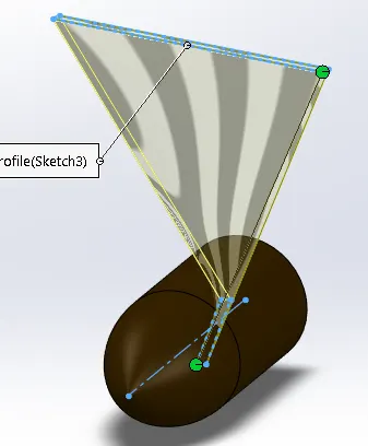
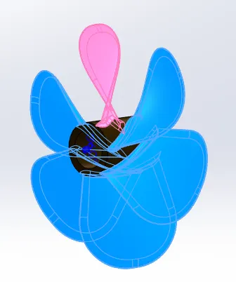
REVOLVE,SPLINE,LINE COMMAND LOFT COMMAND CIRCULAR PATTERN
(2) RADAR {RADIO DETECTION AND RANGING} :- Radars today are used to detect and track aircraft, spacecraft, and ships at sea as well as insects and birds in the atmosphere; measure the speed of automobiles; map the surface of the earth from space; and measure properties of the atmosphere and oceans.
So, here the command and features used in the creation of radar of sunseeker yacht model are :-
A. Boss Extrude Command :- This command in solidwork is used to extrude from 2D sketch into 3D variables in different planes and any direction.
B. Fillet command
C. Cut extrude command
D. Sketch pattern command :-The Sketch Driven Pattern tool is an underused, but very useful tool. Typically, when we pattern items in solidworks we tend to use linear or circular patterns, but what happens when we want to pattern an item where the spacing between instances is irregular or random? That’s where the Sketch driven pattern tool comes into its own.
E. Mirror Command :- Mirror command in solidworks is used to create copy of one or more feature mirrored about a face or a plane.
F. Split line command :- Split Line command is used to project an entity (sketch, solid, surface, face, plane, or surface spline) onto other surfaces or curved/planar faces. You are also able to split faces on multiple bodies with one command.
G. ADDING TEXT ON RADAR :- we can use stick fonts when applying sketch text to parts or assemblies for laser engraving, water jet, and for Computer Numerical Control (CNC) machining.
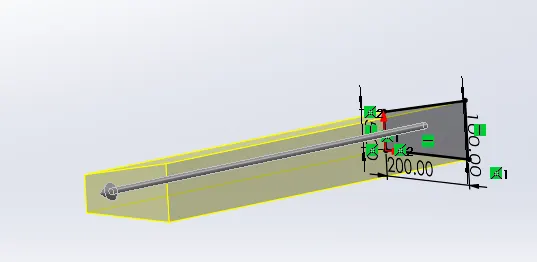
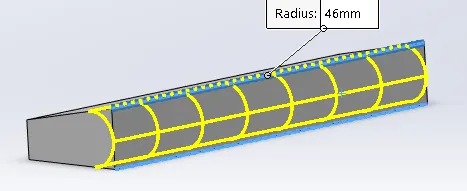
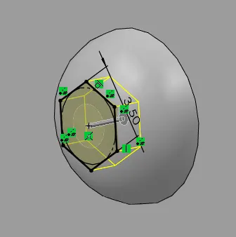
BOSS EXTRUDE COMMAND FILLET COMMAND CUT EXTRUDE COMMAND
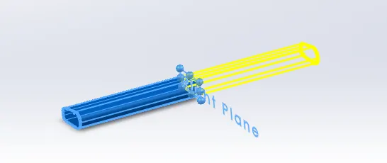
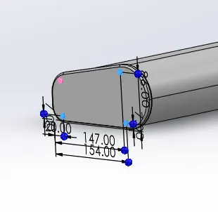
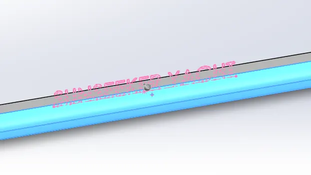
MIRROR COMMAND SKETCH PATTERN COMMAND SPLIT LINE COMMAND
(3) BLUEPRINT SETUP :-
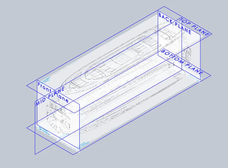
Blueprints are one of the most useful things for modelling an yacht using any 3D software. They are basically the exact orthogonal drawings of the yacht in every direction and dimensions (front, top, side and rear). They allow us to draw curves over a picture so that we can precisely generate the real shape of the yacht.
(4) HULL :- The hull of a boat or a ship is its outer body. A boat's hull can be made of wood, metal, or fiberglass — it gives a boat or ship its shape and keeps water out. Another kind of hull is the outer covering of a seed.
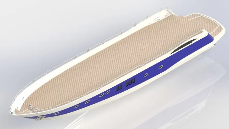
So, here the command and features used in the creation of hull of sunseeker yacht model are :-
A. Sketch:- The sketch tool is used to create 2D drawing of the part in Solidworks. The sketch is the basics of most 3D models. Creating a model usually begins with sketch. From the sketch, one can create features. We can combine one or more feature to make a part. Then, we combine and mate the appropriate parts to create an assembly. From the parts or assemblies, we can then create drawings.
A sketch is a 2D profile or cross section. To create a 2D sketch, we use a plane or a planer face.
B . Spline command :- Splines are used to draw complex curves. Solidworks supports two types of splines, B-splines and style splines. We can use B-splines to create complex curves. One can define and modify them using several controls including spline points, spline handles and control polygons.
C. Centerline command :- Centerlines are annotations that mark circle centers and describe the geometry size on drawings. Centerlines are annotations that mark circle centers and describe the geometry size on drawings. You can insert centerlines into drawing views automatically or manually. The SOLIDWORKS software avoids duplicate centerlines. If you dimension to a centerline, the extension lines are shortened automatically.
D . Trim command :-The Trim Entities tool is mainly used for removing unwanted parts or portions from the design sketch. For trimming, one must have coincident sketch parts with another. The Sketch Trim Entities also consists of “Extend Entities” tool, which help to extend or adjusting the lines. The trimming is like removing unwanted parts using sissors.
E. straight slot :-The straight slots and arc slots are two main type’s slot sketching tools inside SolidWorks sketch. Like different rectangle/arc drawing methods, slot sketching tools contains 3 point and center point drawing methods.
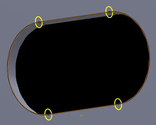
F. 3D sketch tool:-In 3D sketching, a graphical space handle helps maintain the orientation while sketching on several planes. The space handle appears when the first point of a sketch entity is defined on a selected plane. Using the space handle, one can select the axis along which you want to sketch. One can create a 3D sketch with reference to XY, YZ, and ZX planes, axes, or surfaces.
G. Sketch fillet tool:-The Sketch Fillet tool trims away the corner at the intersection of two sketch entities to create a tangent arc. This tool is available for both 2D and 3D sketches.
H. ELLIPSE:-Solidworks has a standard tool for drawing an ellipse. In fact, this tool is more than just drawing standard ellipses.
I. MIRRORING INSIDE SKETCH :- we can mirror solids that contain patterns of features on a face, and the pattern will be updated on both sides. The pattern must be created before the solid is mirrored. The plane becomes a persistent mirror once you create geometry using the mirror. The mirror relationship is maintained when you use other 2D and 3D tools to edit your design. Mirrored components have a mirrored icon in the Structure Tree and maintain their mirror relationships when they are exported. Mirrored objects are created on the same layer as the original object. Mirrored points do not maintain their mirror relationship.
J. PROJECTED CURVE:- The projected curve is a tool which utilizes two different 2D curves on a 2D plane in order to obtain a 3D curve. This is obtained by drawing two 2D curves on two different perpendicular planes. When these two planes are projected perpendicular to each other, their meeting junction will make a curve which is nothing but a projected curve.
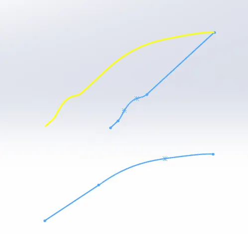
K. Surface Loft Command :- This command in solidwork is used to create loft of surfaces by making transition between multiple profile and guided curves.
L. Surface Trim Command :- In solidworks this command is used to remove two or more surfaces that intersect at one or more points, or remove a surface that intersects with a plane or has a sketch on its face.
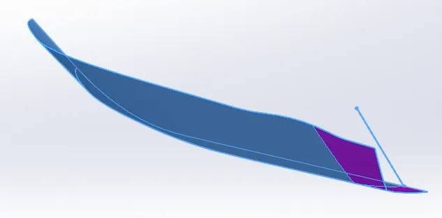
M. SURFACE EXTRUDE COMMAND :- Using the SOLIDWORKS Surface Extrude feature, we can extrude the boundary edges of a face of a solid body or edges of a surface body in a customized direction. When we run the Extruded Surface command, two things can happen: Either a sketch is active or preselected or no sketches exists. In case no sketches exist or is selected, a message in yellow color shows in the property manager window on the left.
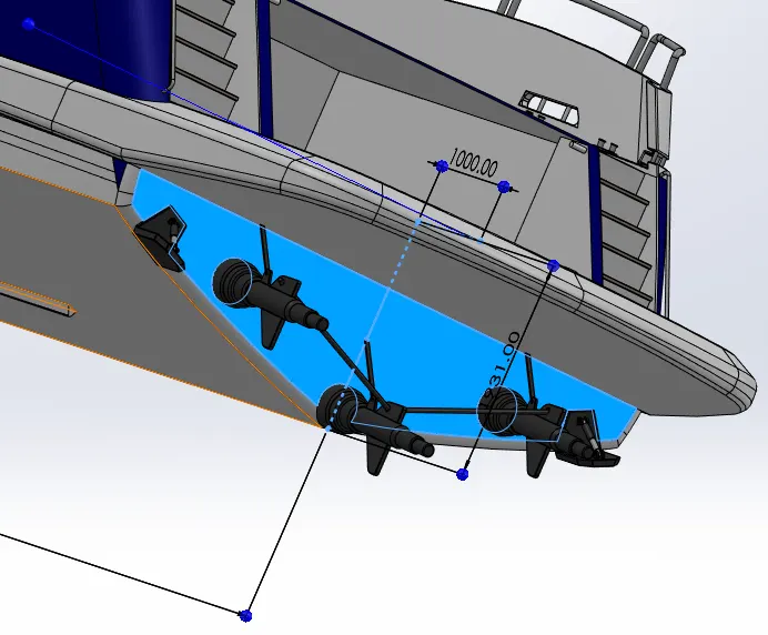
N. Surface Knit Command :- surface knit command in solidworks is used to combine two or more faces and surfaces into one in which the edges of the surface must be adjacent not overlapping and the surfaces must not be on the same planes.
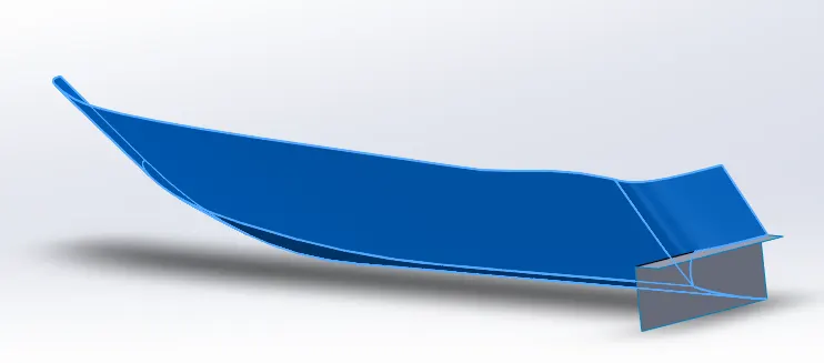
O. SURFACE FILL COMMAND :- The Fill Surface is different from the other types of features like loft, boundary and sweep. The main thing that Fill is supposed to do is to fill an n-sided patch. The patch can be filled with tangency, curvature continuity or simple contact at the edges. The boundary around the Fill can be edges or 2d/3d sketches.
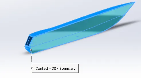
P. Shell Command :- Shell command in solidwork is used to create The shell which hollows out a part, we can create thin- walled features on the remaining faces. also we can shell a solid part, creating a closed, hollow model and can also shell a model using multiple thicknesses.
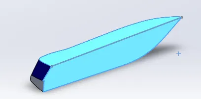
Q. LINEAR PATTERN :- The Linear Pattern is used when we need to pattern one or more features along one or two linear paths. For linear patterning, there is a parent pattern (base pattern) which is used to create the array of patterns in one or two dimensions. The patterns should follow the exact shape of the main pattern. If we do any changes in the base pattern, it will automatically update to other pattern shapes produced from the base patterns.
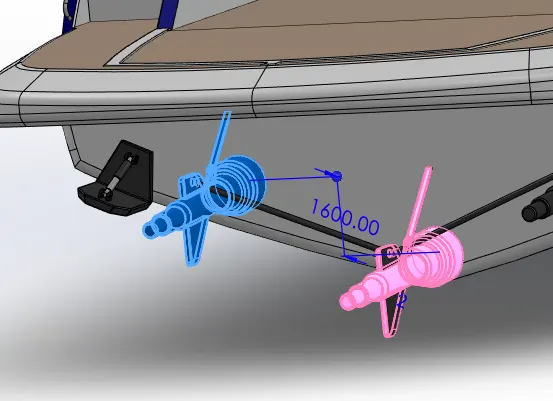
R. SWEEP COMMAND :- The Sweep function within SolidWorks is a powerful command used for multiple purposes. Sweep is the one feature in Solidworks that helps sweep a closed profile along a closed or open path.
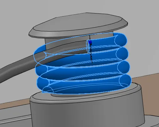
S. DOME COMMAND:- The Dome feature is used to create a small bulge on to the surface of a part thus adding aesthetic looks to the part.
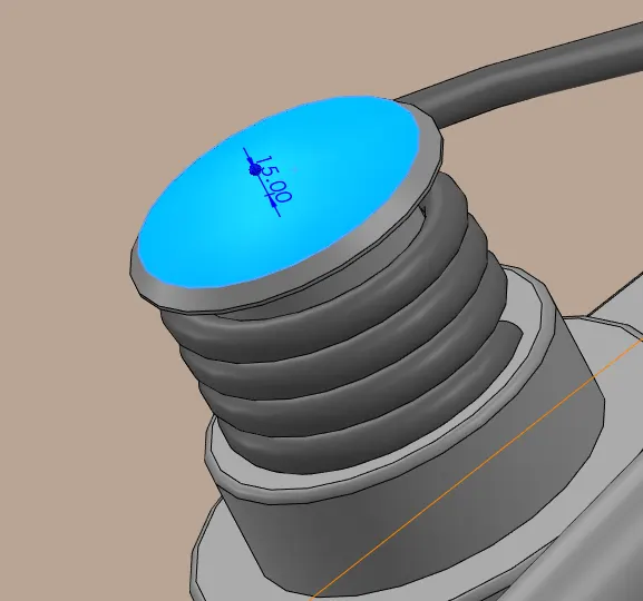
T. CURVES – HELIX / SPIRAL COMMAND :- One can create a helix or spiral curve in a part which can be used as a path or guide curve for a swept feature, or a guide curve for a lofted feature.
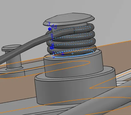
U. DELETING FACE :-The delete face command within Solidworks CAD becomes integral to the modeling process when you are dealing with imported geometry and surfaces. It’s great for removing geometry or enabling edits to existing geometry with no feature history.
OPTIONS AVAILABLE FOR “DELETE FACE” COMMAND:-
- Delete:- This option will remove the selected faces, leaving a void where the face or faces existed previously. If a face is deleted from a solid body, a surface body will be created. This is the quickest way to transform a solid body to a surface body.
- Delete & Patch:- This option deletes a face from a body and automatically patches the void. The edges adjacent to the deleted face will be extended and then trimmed, leaving a distinct edge.
- Delete & Fill :- This option deletes the selected faces and replaces them with a single unbroken face. The fill also has the option for tangent fill. With this option selected, the filled face will use tangent edges. With the option cleared the replacement face will use contact edges.
Since the Delete Face Command isn’t on any standard toolbars, the easiest way to access it is to customize your interface and add it to the features ribbon. However, you can always access the command by searching for it with the Command Search.
V. COMBINE :-The Combine function in solidwork allows us to add two bodies together, and keep the area that is common to them.
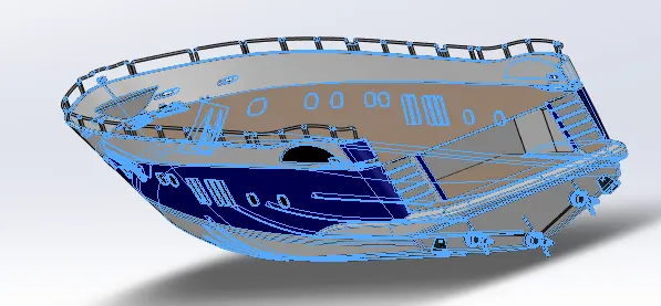
W. THIN EXTRUDE :- The Thin Feature tool takes the sketched profile and creates a constant thickness in the sketch plane. One good example of this is a hollow tube. Instead of creating two circles in the sketch, you can just sketch one and then specify the thickness within the Extrude.
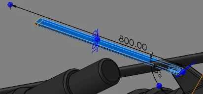
X. SPLIT COMMAND :- The Split tool is used to separate a part into two or more bodies.
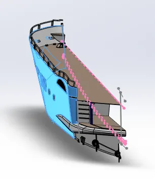
Y. CHAMFER :- The chamfer tool creates a beveled feature on selected edges, faces, or a vertex.
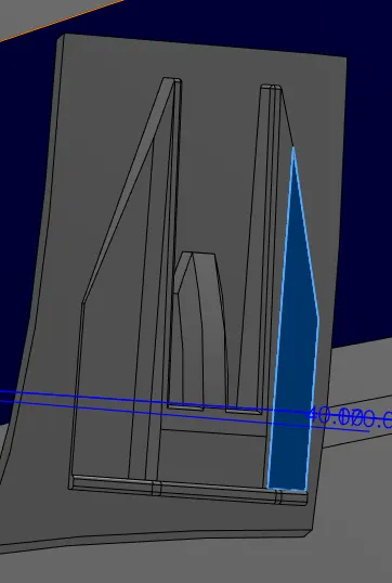
Z. Pierce Tool :- This tool in solidworks is used to snap a point of geometery to the another geometery in different plane.eg:- snaping the centre of any circle to the combine or projected curve.
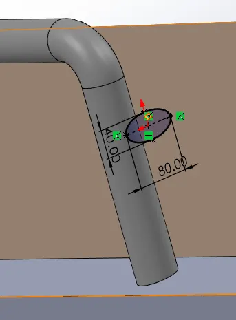
(5). FRONT SEATS :- Marine passenger seats and chairs can be used on the fast ferry, high-speed passenger ship, cruise ship, catamaran, crew boat,, cargo ship, the sightseeing boat, traffic boat, pilot launch, yacht and other passenger vessels. The material of the seats adopt fire-proof leather, PU/PVC leather or fabric according to customer’s requirements. The anti-corrosion aluminum structure is durable. They all have beautiful appearance and special design which makes people more comfortable when seating.
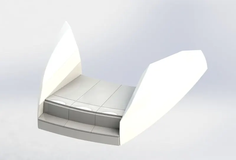
So, all the command and features used in the creation of front seats of sunseeker yacht model are discussed above.
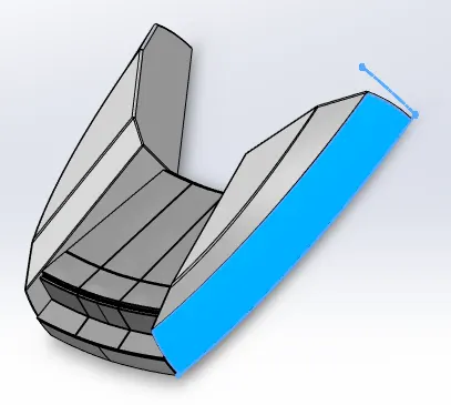
A. SURFACE SWEEP:- Swept surfaces give you the tools to drag a given profile along a path to create a shape.
B. Offset Entities :- This command in solidworks is used to offset various geometries to various dimensions in different planes and any direction.
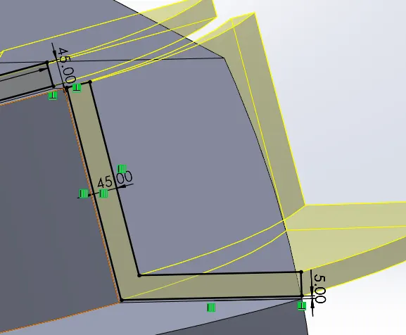
else, other commands used in the creation of front seats of sunseeker yacht are discussed in above parts.
(6) MIDDLE SEATS :- Marine passenger seats and chairs can be used on the fast ferry, high-speed passenger ship, cruise ship, catamaran, crew boat,, cargo ship, the sightseeing boat, traffic boat, pilot launch, yacht and other passenger vessels. The material of the seats adopt fire-proof leather, PU/PVC leather or fabric according to customer’s requirements. The anti-corrosion aluminum structure is durable. They all have beautiful appearance and special design which makes people more comfortable when seating.
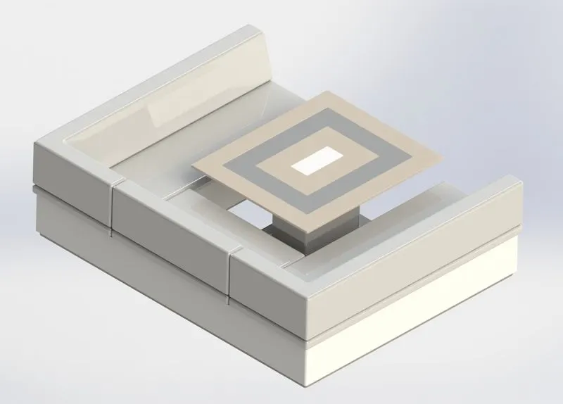
So, here the command and features used in the creation of MIDDLE seats of sunseeker yacht model are :-
A. CONVERT ENTITIES COMMAND :- Convert Entities command in solidworkis used to create one or more curves in a sketch by projecting an edge, loop, face, curve, or external sketch contour, set of edges, or set of sketch curves onto the sketch plane.
else, other commands used for creation of this part are discussed above.
(7) REAR SEATS :- Marine passenger seats and chairs can be used on the fast ferry, high-speed passenger ship, cruise ship, catamaran, crew boat,, cargo ship, the sightseeing boat, traffic boat, pilot launch, yacht and other passenger vessels. The material of the seats adopt fire-proof leather, PU/PVC leather or fabric according to customer’s requirements. The anti-corrosion aluminum structure is durable. They all have beautiful appearance and special design which makes people more comfortable when seating.
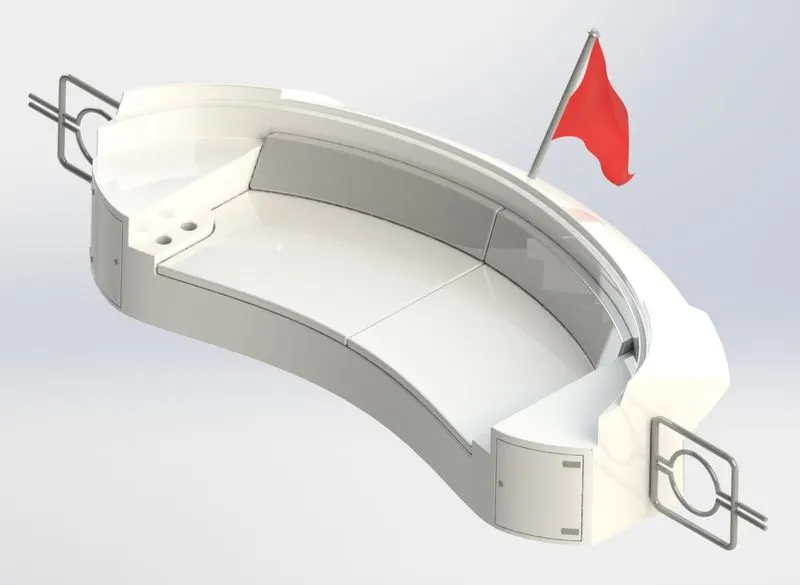
So, here the command and features used in the creation of MIDDLE seats of sunseeker yacht model are :-
A. CORNER RECTANGLE :- The corner rectangle is a simple sketch tool in which the rectangle is drawn initially from corner to corner. By clicking on a point inside sketch, the first corner of the rectangle is fixed and its diagonally opposite corner is dragged to the required size. Afterwards the dimensions are given to constrain the sketch.
B. SURFACE OFFSET :-A common technique for advanced surfacing modeling is using the Surface Offset command. In SOLIDWORKS, the command gives users the option to SEE and REMOVE any surfaces that cannot be offset, building the remaining geometry.
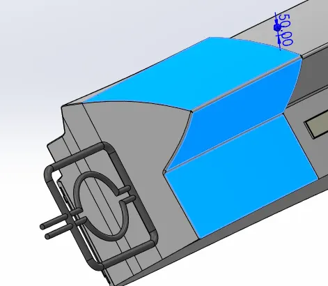
C. RULED SURFACE :- The Ruled Surface command is a very versatile command that can create several different types of surfaces. It will create surfaces at an edge relative to an existing surface. All it takes is just an edge and a user input distance. With that, the Ruled Surface can add new surface geometry in the following ways:
- Tangent to Surface
- Normal to Surface
- Tapered to Vector
- Perpendicular to Vector
- Sweep
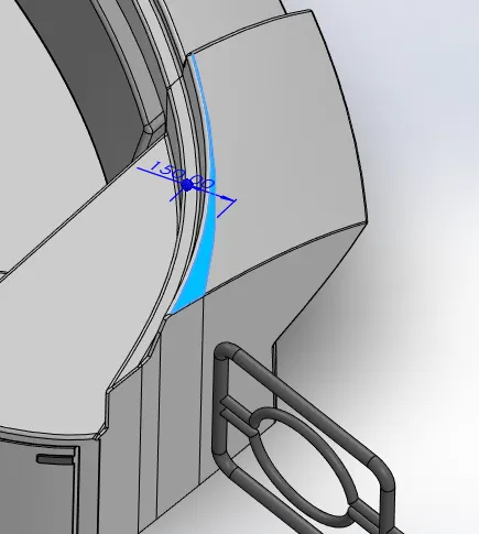
D. SURFACE EXTEND:- Extension of the surface is an operation that allows you to extend a surface by a given distance, to a point or to another surface. You can select the entire surface area or an edge . Depending on the geometric conditions, the operation will succeed or fail, this is especially true for high elongation values with complicated curvature. It is easy to recognize, because the preview disappears.
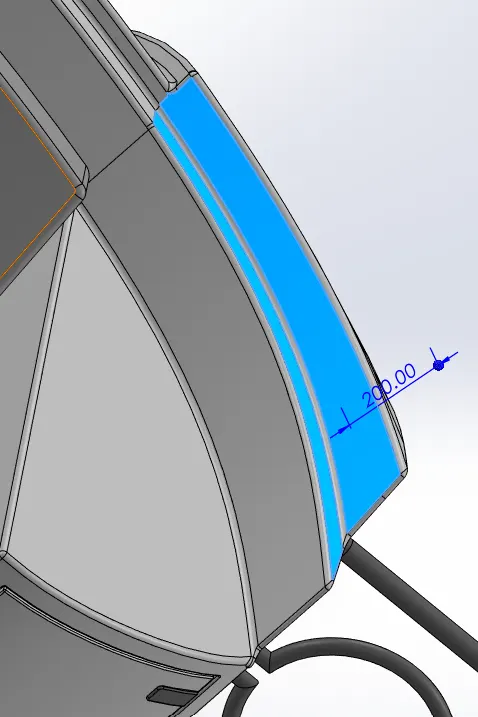
F. CONVERT ENTITIES COMMAND :- Convert Entities command in solidworkis used to create one or more curves in a sketch by projecting an edge, loop, face, curve, or external sketch contour, set of edges, or set of sketch curves onto the sketch plane.
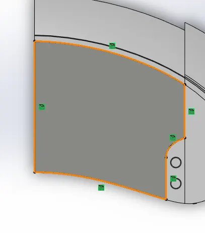
else, other command and features used for creation of this part are discusse above.
(8) SUPERSTRUCTURE :-On water craft, the superstructure consists of the parts of the ship or a boat, including sailboats, fishing boats, passenger ships, and submarines, that project above her main deck. This does not usually include its masts or any armament turrets.
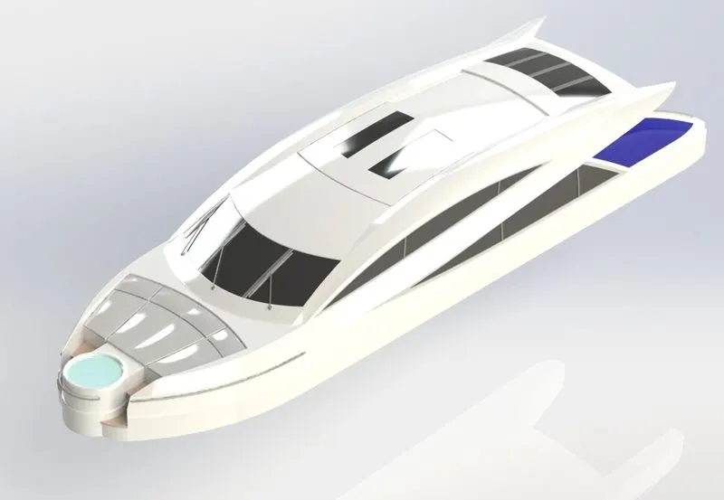
So, here the command and features used in the creation of SUPERSTRUCTURE of sunseeker yacht model are :-
A. SPLIT ENTITIES :- The SOLIDWORKS Split Line tool is used to project an entity (sketch, solid, surface, face, plane, or surface spline) onto other surfaces or curved/planar faces. You are also able to split faces on multiple bodies with one command.
B. CENTERPOINT ARC :- Solidworks provides various kinds of methods and commands to draw arcs inside it. This arc drawing command called Centerpoint Arc is one of them. The Centerpoint Arc tool is used to draw an arc by defining the center point, start point and endpoint.
C. THICKEN THE SURFACE :-Thicken takes a surface body (which has zero thickness) and makes it a solid (making it a volume) by specifying a thickness value and side to thicken. Until now, the calculation was based on surface normal, which is often what you want. Now, though, we can specify a direction for the offset created by the Thicken command.
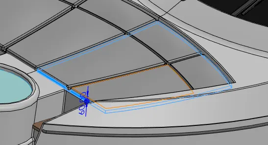
D. CORNER RECTANGLE :- The corner rectangle is a simple sketch tool in which the rectangle is drawn initially from corner to corner. By clicking on a point inside sketch, the first corner of the rectangle is fixed and its diagonally opposite corner is dragged to the required size. Afterwards the dimensions are given to constrain the sketch.
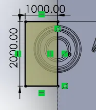
else, other commands used for creation are discusse above.
(9) GARAGE DOOR :- A garage door is a large door on a garage that opens either manually or by an electric motor (a garage door opener). Garage doors are frequently large enough to accommodate automobiles and other vehicles. Small garage doors may be made in a single panel that tilts up and back across the garage ceiling.
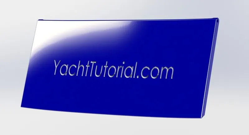
So, here the command and features used in the creation of garage door of sun seeker yacht are discussed in above parts.
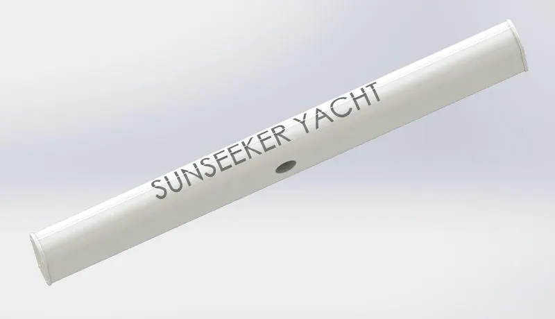
(10) RADAR MAST :- They are electronic navigation instruments that use a rotating antenna to sweep a narrow beam of microwaves around the water surface surrounding the ship to the horizon, detecting targets by microwaves reflected from them, generating a picture of the ship's surroundings on a display screen.
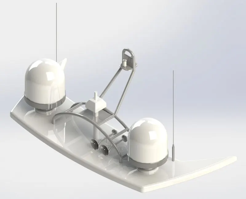
So, the commands and features used in the creation of radar mast of sun seeker yacht are discussed in above parts.
# APPEARENCE TOOL IN SOLIDWORKS :- An appearance defines the visual properties of a model, including color and texture. Appearances do not affect physical properties, which are defined by materials. Every material is assigned a default appearance that emulates the look of the material.
(11) ASSEMBLY OF SUNSEEKER YACHT MODEL :- You can build complex assemblies consisting of many components, which can be parts or other assemblies, called subassemblies. For most operations, the behavior of components is the same for both types. Adding a component to an assembly creates a link between the assembly and the component.
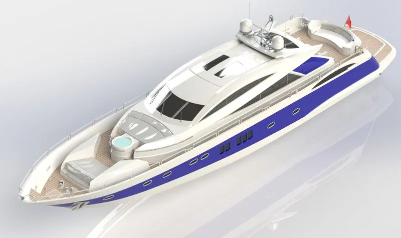
So, here the commands and features used for the assembly of sunseeker yacht model are :-
MATES IN ASSEMBLY OF MODEL :-
A. CONCIDENT MATE :- A coincident mate, like the name sounds, is a mate between two features that you want to coincide with each other. Generally we use it for making two planes parallel and coincident.
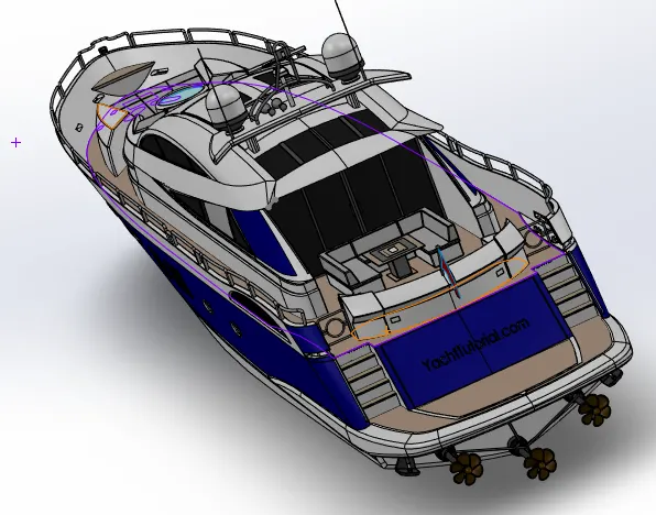
B. CONCENTRIC MATE :- Concentric mates allow you to align the axis of a curved or cylindrical face with the axis of another. This mate is ideal for aligning holes and other curved faces.
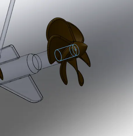
C. DISTANCE MATE :-A distance limit mate allows two surfaces or points to move along a single axis to a maximum and minimum distance.
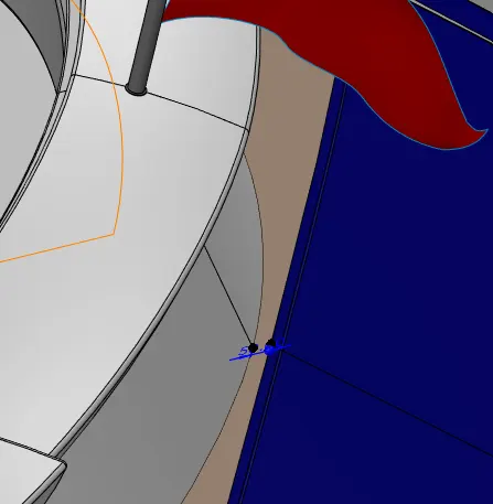
(12) RENDERING OF SUNSEEKER YACHT MODEL :-
A. RENDERING USING SOLIDWORKS PHOTOVIEW 360 :-
Rendering or image synthesis is the process of generating a or non photorealistic image from a 2D or 3D model by means of a computer program. The resulting image is referred to as the render. Multiple models can be defined in a scene file containing objects in a strictly defined language or data structure. The scene file contains geometry, viewpoint, texture, lightning, and shading information describing the virtual scene. The data contained in the scene file is then passed to a rendering program to be processed and output to a digital image or raster graphic image file. The term "rendering" is analogous to the concept of an artistis impression of a scene. The term "rendering" is also used to describe the process of calculating effects in a video editing program to produce the final video output.
a. APPLYING DECALS & LIGHTS INSIDE SOLIDWORKS USING PHOTOVIEW 360 :-
Photoview 360 is a SolidWorks add-in that produces photo-realistic renderings of SolidWorks models. The rendered image incorporates the appearances, lighting, scene, and decals included with the model. Photoview 360 is available with SolidWorks Professional or SolidWorks Premium.
b. ADDING DECALS TO FLOOR SURFACES OF THE HULL, FLOOR SURFACE OF THE GARAGE AND THE FLOOR SURFACE ALONG STEPS:-
Decals are the design prepared on special paper for durable transfer on to another surface such as glass or porcelain. Here the decals are applied onto the floor surfaces of the hull, floor surface of the garage and the floor surface along the steps.
c. ADJUSTING COLORS AND EDITING MATERIALS :-
The colors for propellor, RADAR, Hull, Rear Seat, Middle Seat, Front Seat, Superstructure, and Radar mast are modified corresponding to one’s taste. The material is also modified correspondingly.
d. ADDING LIGHTS AND BACKGROUND IMAGES :-
The background images and lights are added corresponding to one’s likeness. Here we can change the lights and their position which we can fix it in position. Also, one can include different HD 3D image in the background.
e. RENDERING LIGHTS :-
We can either suppress lights or enable them. They add luminescence to the 3D model. There are four available lights inside Solidworks
- Directional Lights
- Point Lights
- Spot Light &
- Sun Light.
For Sunseeker Predator Yacht, we choose Directional Lights.
f. CAMERA SETUP AND SCENE CREATION :-
The main reason for undergoing this step is to make sure that the model rendered might look realistic. As regards the Sunseeker Predator Yacht, its hull should touch the sea level. Also, the yacht should lean on one side so that the yacht may look real when rendered. These are the process which are carried out before going for rendering.
g. CREATING CAMERAS :-
The rendering will be looking more realistic if we add cameras to the view. This will make the 3D model more visible along the direction in which we want to view it. A camera can be added by selecting Main Menu – View – Lights and Cameras – Add Camera.
The camera can be turned along all three axis and it focal point can also be adjusted.
h. CHANGING THE SCENE COMPOSITION :-
To make the 3D model as realistic as possible, we add a 3D picture image and change the scene composition correspondingly. One should make sure of turning on the perspective view.
i. FINAL RENDERING :-
Under Render tools, if clicked on Render Preview – one can preview the rendered image inside Solidworks window. Any correction if required, can be made correspondingly. Also, a comparison can be made between previous rendered image and the recent one and hence it will help in coming to a conclusion while selecting an image which can be well rendered.
FINAL RENDERED IMAGES USING PHOTOVIEW 360 :-
FRONT VIEW :-
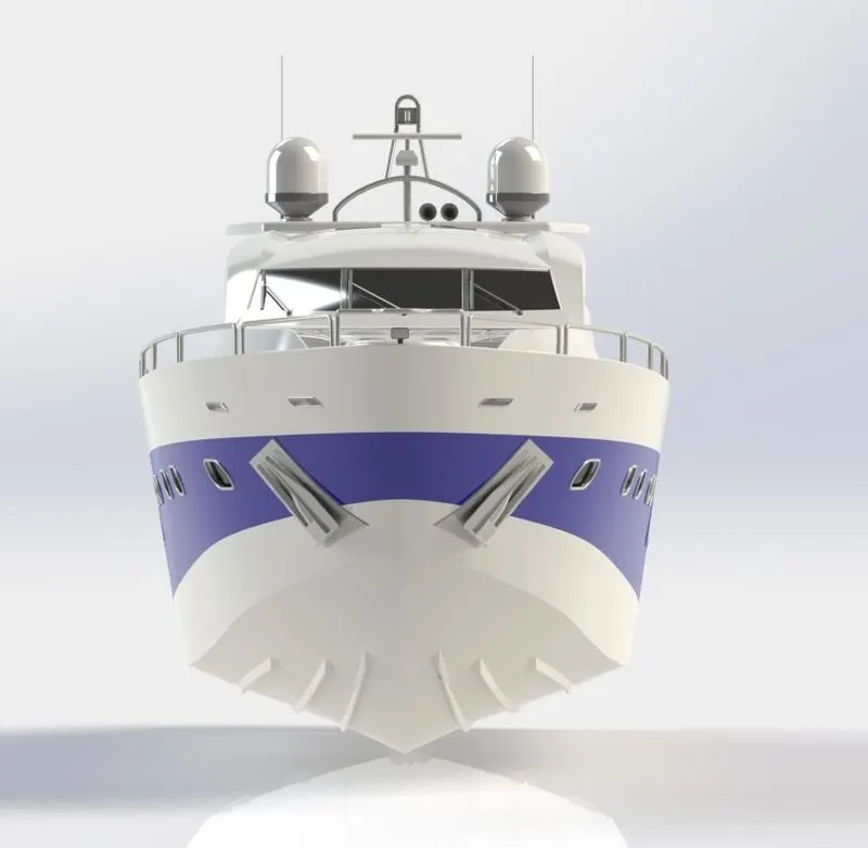
SIDE VIEW :-
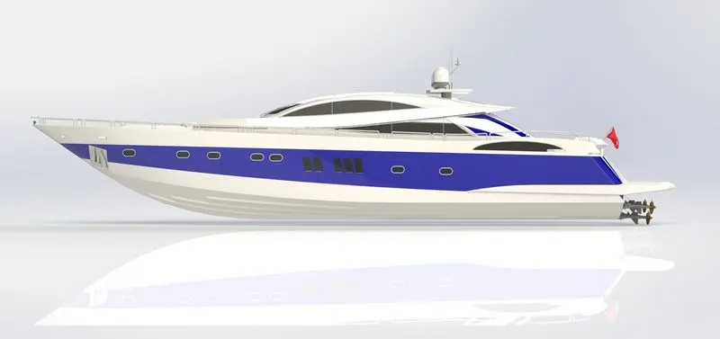
ISOMETRIC VIEW :-
TOP VIEW :-
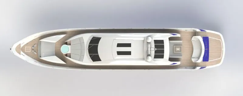
BACK VIEW :-
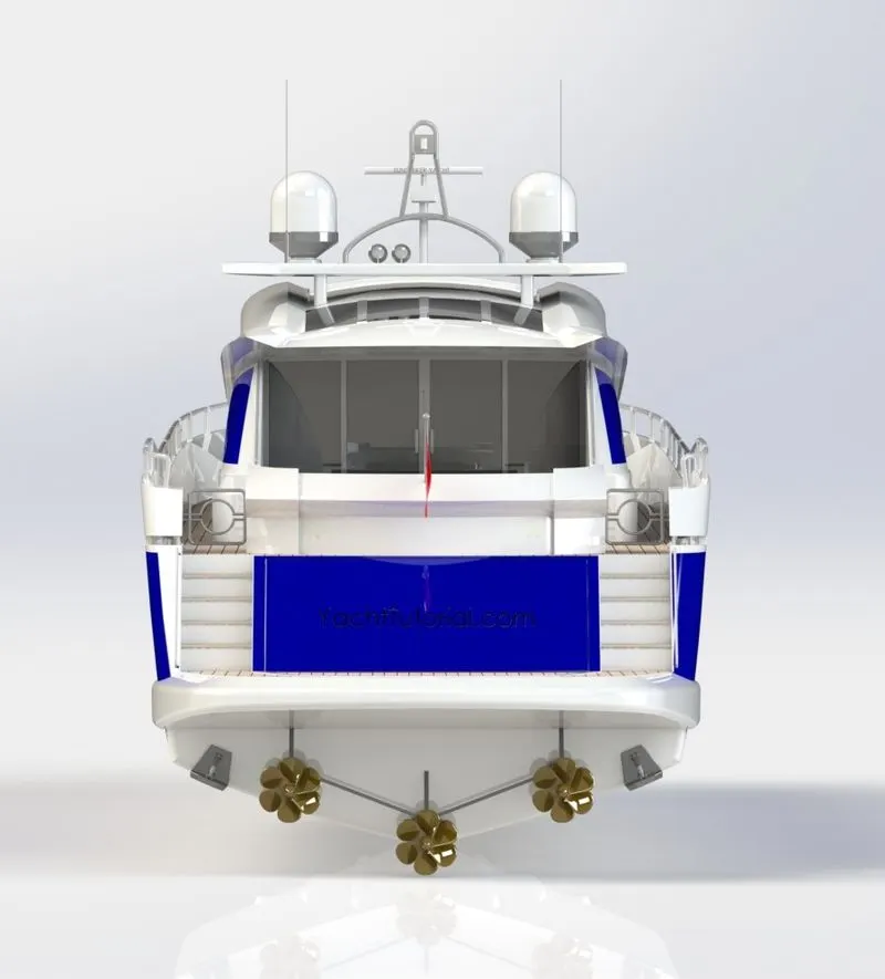
B. RENDERING USING SOLIDWORKS VISUALIZE :-
The Solidworks is a tool which is used to create Solidworks rendering. We import models into Solidworks visualize the we group them based on appearance or by different types of hierarchy or by entire assembly. After opening Solidworks visualize, click on new project – go to “Import models and parts” and then browse for “Assembly” of American chopper. Next open “Import Settings” and under Import Settings we have four tabs
- Geometry
- Appearances
- Environments
- Decals
Change the required parameters correspondingly.
a. SETUP AND SCENE CREATION:-
Right click on new appearances and delete it. Go to “File Libraries” tab – here we can change the material, paint and scenes correspondingly instead of changing one by one parameters in appearance tab.
b. FINAL RENDERING:-
After making all these changes, we click on the Accurate render to initialize the rendering mechanism at an accurate level. The time for rendering depends entirely upon the no of passes given. More the no of passes more will be the time taken to complete rendering process.
FINAL RENDERED IMAGES USING SOLIDWORKS VISULIZE :-
A. CAMERA VIEW :-
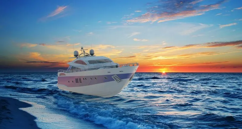
B. FRONT VIEW :-
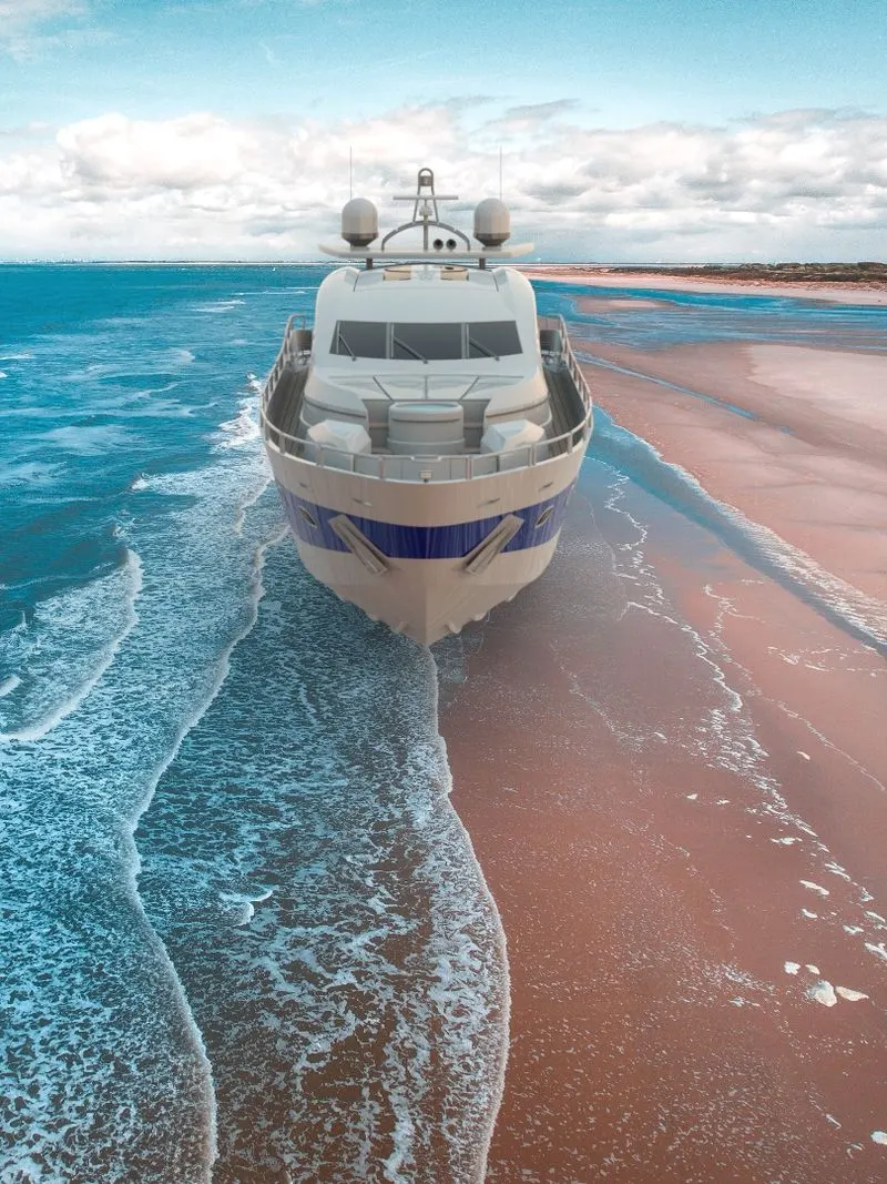
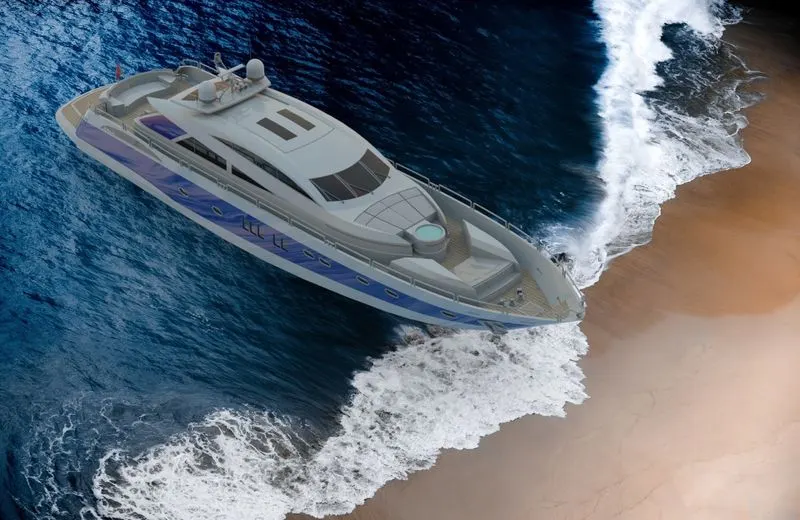
C. ISOMETRIC VIEW :-
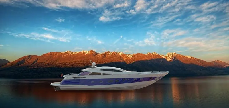
D. SIDE VIEW :-
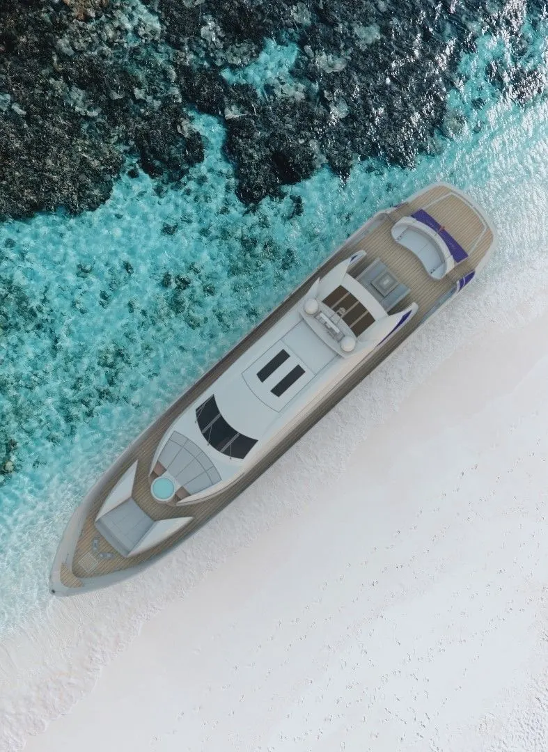
E. TOP VIEW :-
Conclusion :-
After modeling of Yacht, I have learnt different tools used in SOLIDWORKS. Also, tools related to assembly and rendering.