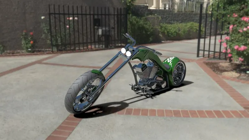
Photo Realistic Rendering
1. TITLE :- DESIGNING OF ALL THE PARTS AND ASSEMBLY OF AMERICAN CHOPPER MODEL USING SOLIDWORKS MODEL
2. OBJECTIVE :- DISIGNING OF ALL THE PARTS AND ASSEMBLY OF AMERICAN CHOPPER MODEL USING VARIOUS COMMANDS AND FEATURES IN SOLIDWORKS.
3. INTRODUCTION :-
American Chopper is a two wheeler. I used Solidworks to design American Chopper. There are different modules in Solidworks which are used to design different component.
(1). Computer Aided Design (CAD)software like Solidworks is very simple to use for the creation of 3D solid model and can be created faster. The main advantage of Solidworks is that everyone can use it as compared to other cad software.
(2). Solidworks is mainly used in many industries for the design and assembly of there product due to which productivity increases and the cost is also less. With the equation tool in Solidworks it is easy to write all the global variables and
evaluate the dimension through global variables.
4.DESIGN METHODOLOGY/APPROACH :-
Different components of American Chopper are given below in table with their use:-
| Item No. | Part Name (Figure No.) | Use of Part |
| 1. | Transmission Belt of American Chopper (Figure 1) | Transmit power |
| 2. | Pedal of American Chopper (Figure 2) | Rest for Leg |
| 3. | Rear Wheel of American Chopper (Figure 3) | Power wheel |
| 4. | Rear Fender of American Chopper (Figure 4) | Avoid from Mud |
| 5. | Oil Tank of American Chopper (Figure 5) | Store Lubricant |
| 6. | Stand of American Chopper (Figure 6) | Stand to Surface |
| 7. | Gas Tank of American Chopper (Figure 7) | Store Fuel |
| 8. | Front Wheel of American Chopper (Figure 8) | Guide Wheel |
| 9. | Front Fork of American Chopper (Figure 9) | Control Direction |
| 10. | Front Fender of American Chopper (Figure 10) | Avoid from Mud |
| 11. | Chassis of American Chopper (Figure 11) | Mount all Components |
| 12. | Engine of American Chopper (Figure 12) | Power House of Vehicle |
| 13. | Chain of American Chopper (Figure 13) | Transmit power |
| 14. | American Chopper (Figure 14) | Transportation |
5. DESCRIPTION :-
In Solidworks, we use different module for different purpose. Here we use Sketch Module, Surface Module,
Features Module, Evaluate Module, Render Module, Solidworks Visualize Module, etc. for designing American
Chopper.
(1) Sketch Module :- In Sketch Module, we use Line Command, Rectangle Command, Circle Command, Arc Command,
Spline Command, Fillet Command, Chamfer Command, Point Command, Trim Entities, Convert Entities,
Offset Entities, Mirror Entities and Pattern Command.
(2) Surface Module :- In Surface Module, we use Extruded Surface Command, Revolved Surface Command, Swept Surface
Command, Lofted Surface Command, Boundary Surface Command, Filled Surface Command, Planar Surface Command, Offset Surface Command, Extend Surface Command, Trim Surface Command, Untrim Surface
Command, Knit Surface Command, Freeform Command, Thicken Command, Fillet Command, Chamfer
Command, Reference Geometry and Curves.
(3) Feature Module :- In Features Module, we use Extruded Command, Revolved Command, Swept Command, Lofted Command,Boundary Command, Extruded Cut Command, Revolved Cut Command, Swept Cut Command, Lofted Cut
Command, Boundary Cut Command, Hole Command, Fillet Command, Chamfer Command, Pattern Command,Dome Command, Draft Command, Shell Command,Mirror Command, Move Command, Reference Geometry, Curves, Split Command and Combine Command.
(4) Evaluate Module :- In Evaluate module of solidworks it is used for evaluation,simulation and flow simulation of the entire model.
(5) Render Module and SW Visualize Module :- This module in photoview 360 and solidworks visualize is used to properly render images of the model and also used for setting up the scene and the enviornments , camera setup,prespective vision and lights setup for better visuals of the model created in solidworks.
6. COMPONENTS OF AMERICAN CHOPPER :-
(1) Transmission Belt :-
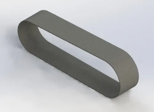
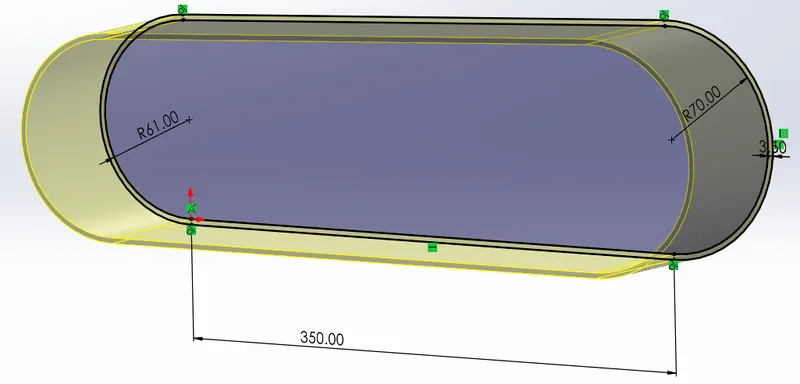
So, here the command and features used in the creation of transmission belt of american chopper model are :-
A. Line Command:- line command is solidwork is used to create line from one end point to other end point in different planes and in any direction. as shown in the sketch image.
B. Arc command :- Arc command in solidwork is used to create arc from one point to another point of different radius and diameter in different planes and any direction .
C. Offset Entities :- This command in solidworks is used to offset various geometries to various dimensions in different planes and any direction.
D. Boss Extrude Command :- This command in solidwork is used to extrude from 2D sketch into 3D variables in different planes and any direction.
E. Fillet Command :- Fillets command in solidwork is used to placed feature that round off or cap interior or exterior corners or features of a part. You can create: Edge fillets Based on selected edges.
Various commands such as line command , arc command , offset commands , Boss Extrude command were shown in the figure.
(2) Pedal :-
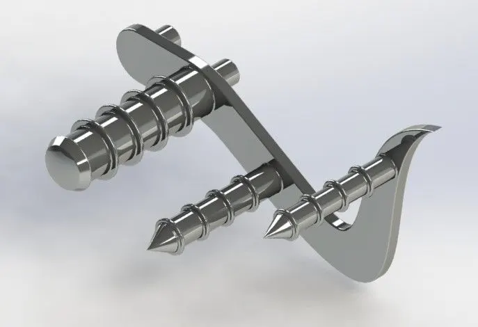
So, here the command and features used in the creation of pedal or footrest of american chopper model are :-
A. Spline Command :- Splines command in solidworks is used to create complex curves. You can define and modify them using several controls, including spline points, spline handles, and control polygons.
B. Circle Command :- Circle command in solidworks is used to create circle of various diameter and radius in different planes and in any direction.
C. Revolve Command :-Revolve command in solidwork is used to create a sketch that contains one or more profiles and a centerline, line, or edge to use as the axis around which the feature revolves.
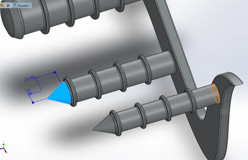
D. Chamfer Command :-The chamfer tool in solidwork is used to create a beveled feature on selected edges, faces, or a vertex of various dimensions.
E. Dome Command :- Dome command in solidworks is used to create Dome on different faces and surfaces of the part of different dimensions.
F. Linear Pattern Command :- linear patterns command in solidworks is used to create multiple instances of one or more features that you can space uniformly along one or two linear paths by selecting the entities to pattern.
Chamfer command is shown in figure and various commands are used in creation of pedal which is discussed earlier.
(3) Rear Wheel :-
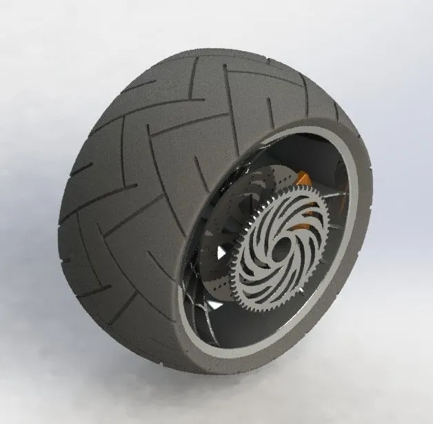
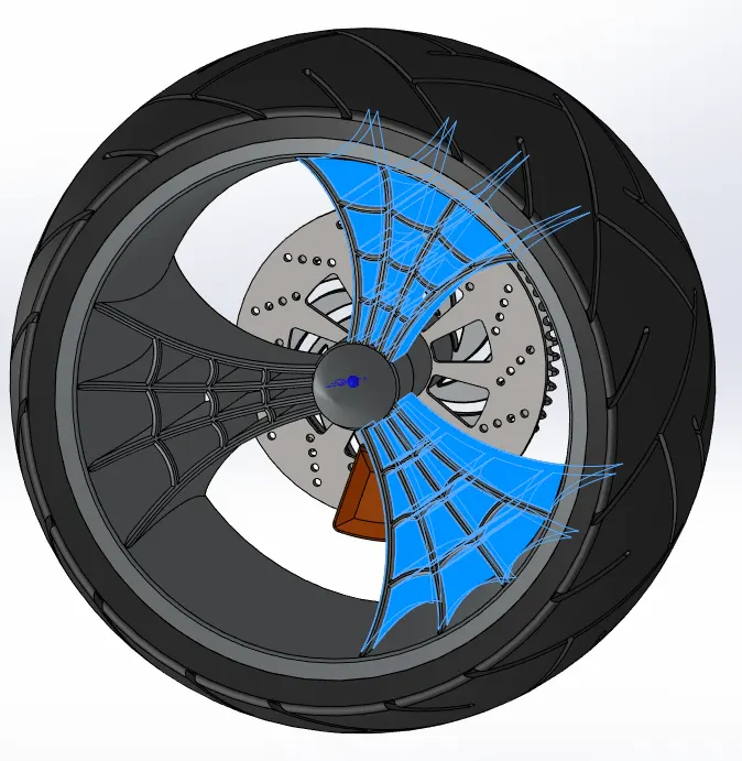
So, here the command and features used in the creation rear wheel of american chopper model are :-
A. Trim Command :- Trim command in solidwork is used to trim multiple edges and adjacent sketch entities.
B. Convert Entities Command :- Convert Entities command in solidworkis used to create one or more curves in a sketch by projecting an edge, loop, face, curve, or external sketch contour, set of edges, or set of sketch curves onto the sketch plane.
C. Cut Extrude Command :- Extruded cut feature in solidwork is used to remove material from the part. The End Condition, Draft, and Thin Feature options are same as described in Extruded Boss/Base.
D. Cut Revolve Command :-Revolved Cut command in solidwork used for the cutting material from a 3D geometry. It is working as Revolved Boss/Base but the difference is, it is used for cutting from 3D geometries.
E. Combine Command :-The Combine function in solidwork allows us to add two bodies together, and keep the area that is common to them.
F. Circular Pattern Command :- Circular patterns command in solidwork is used to create multiple instances of one or more features that you can space uniformly around an axis. Pattern instances inherit the feature color of the original feature when the: Pattern is based on one feature.
G. Rectangle Tool :- This tool in solidworks is used to create various type of rectangles.
Circular pattern command is shown in figure and various commands are used in creation of rear wheel which is discussed earlier.
(4) Rear Fender :-
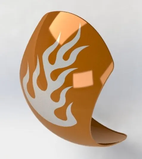
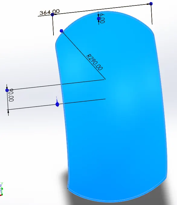
So, here the command and features used in the creation rear fender of american chopper model are :-
A. Split Command :- Split command in solidwork is used to create split of multiple parts from an existing part. We can split on one or more solid or surface bodies. To split a surface, the Trimming Surface must extend past the boundaries of the surface to split.
B. Shell Command :- Shell command in solidwork is used to create The shell which hollows out a part, we can create thin- walled features on the remaining faces. also we can shell a solid part, creating a closed, hollow model and can also shell a model using multiple thicknesses.
Revolve Command is shown in figure and various commands are used in creation of rear fender which is discussed earlier.
(5) Oil Tank:-
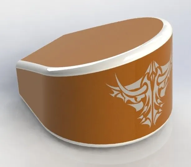
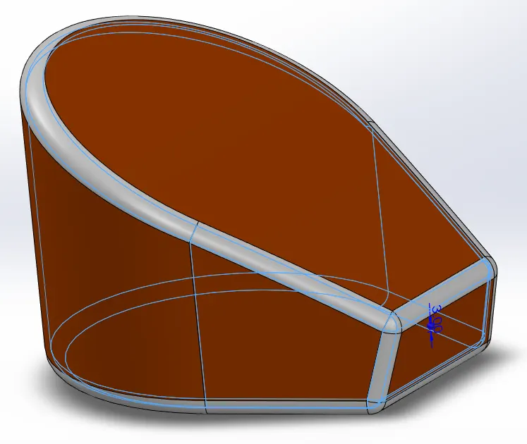
So, here the command and features used in the creation oil tank of american chopper model are :-
A. Combine Command
B. Boss Extrude Command
C. Shell Command :- Shell command is displayed in the figure.
D. Fillet Command
And various commands are used in creation of Oil Tank which is discussed earlier.
(6) Kickstand :-
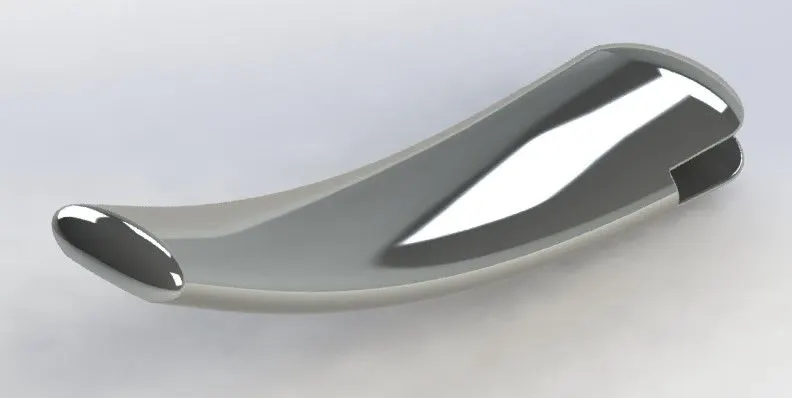
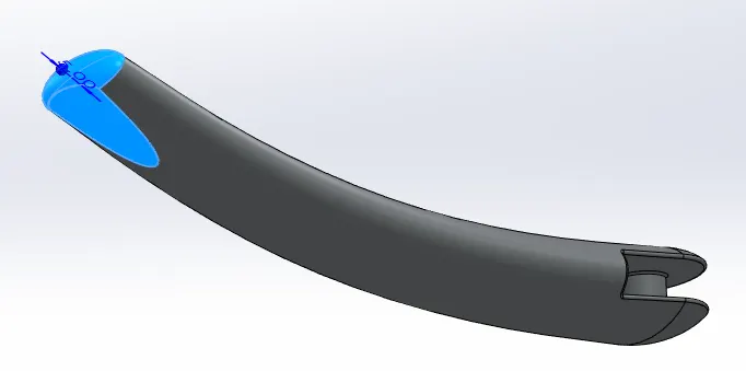
So, here the command and features used in the creation kickstand of american chopper model are :-
A. Loft Command :- Loft command in solidworks creates a feature by making transitions between profiles. A loft can be a base, boss, cut, or surface. where we cn create a loft using two or more profiles.
B. Dome command :- Dome is shown in the above figure.
C. Split command :- Displayed in the figure on the bottom surface of kickstand.
D. Cut/Boss Extrude
And various commands are used in creation of kickstand which is discussed earlier.
(7) Gastank :-

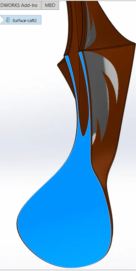
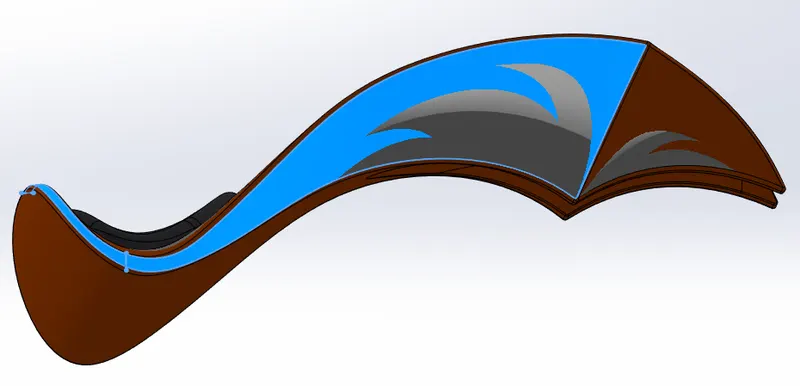
So, here the command and features used in the creation gas tank of american chopper model are :-
A. Surface Sweep Command :- Sweep Surfaces are surfaces that are generated from a section curve positioned along a path. Sweep by Two Guide Curves is defined as moving and adjusting a section curve along two guide curves.
B. Surface Trim Command :- In solidworks this command is used to remove two or more surfaces that intersect at one or more points, or remove a surface that intersects with a plane or has a sketch on its face.
C. Boundary Surface Command :- boundary surface feature in solidworks helps us to create surfaces that can be tangent or curvature continuous in both directions (all sides of the surface).
D. Surface Knit Command :- surface knit command in solidworks is used to combine two or more faces and surfaces into one in which the edges of the surface must be adjacent not overlapping and the surfaces must not be on the same planes.
E. Surface Loft Command :- This command in solidwork is used to create loft of surfaces by making transition between multiple profile and guided curves.
F. Curve Command :- Curve Command in solidworks is used to create curve from one endpoint to another end by means of different sketch's on two different planes.
G. Mirror Command :- Mirror command in solidworks is used to create copy of one or more feature mirrored about a face or a plane.
H. Cut Sweep Command :- Cut Sweep Command is mainly used to cut a solid model or part by sweeping a completely closed profile along an open or closed path.
Boundary surface and surface loft commands are shown in figure and various commands are used in creation of Gastank which is discussed earlier.
(8) Front Wheel :-
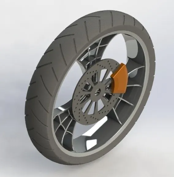
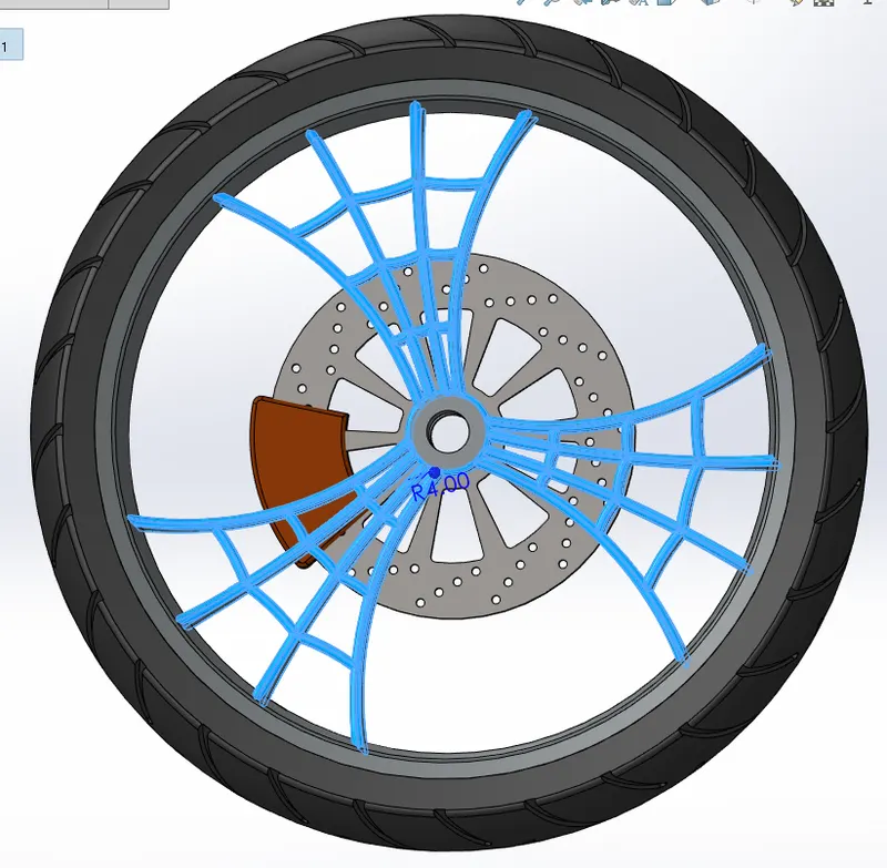
So, here the commands and features used in the creation Front wheel of american chopper model are :-
Boss/Cut Extrude,Revolve,Fillet,Chamfer,Combine...ETC.
Fillet command is displayed in the above figure and various commands are used in creation of Front Wheel which is discussed earlier.
(9) Front Fork :-
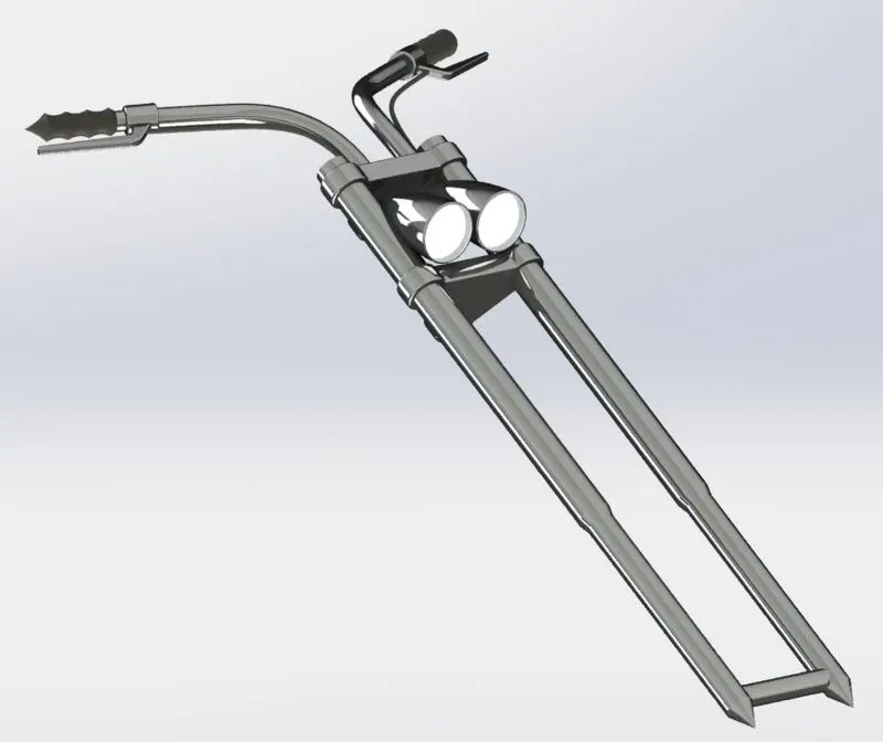
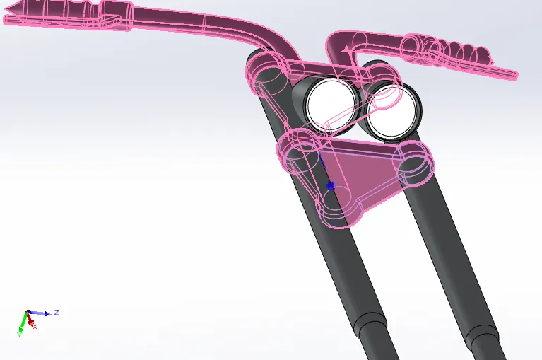
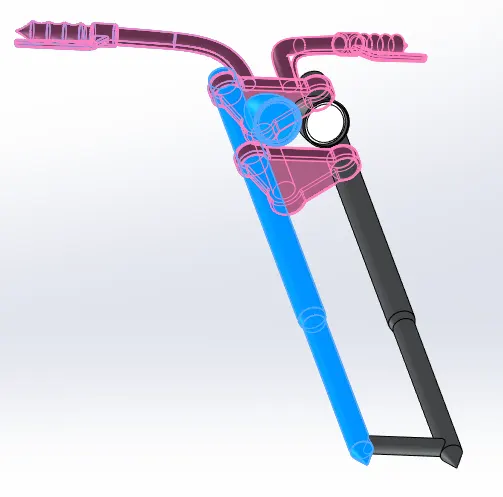
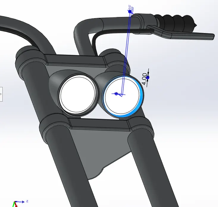
So, here the command and features used in the creation Front Fork of american chopper model are :-
A. Body Move/Copy Command :- This command in solidwork is used to move or copy the bodies accosiated with the part.
Linear pattern, Mirror , Cut Extrude commands are shown in figure. Else, various commands were use in the creation of front fork which is explained in above parts.
(10) Front Fender :-
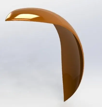
All the commands used in the creation of front fender is explained in above parts.
(11) Chassis :-
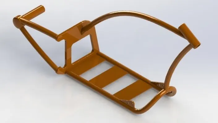
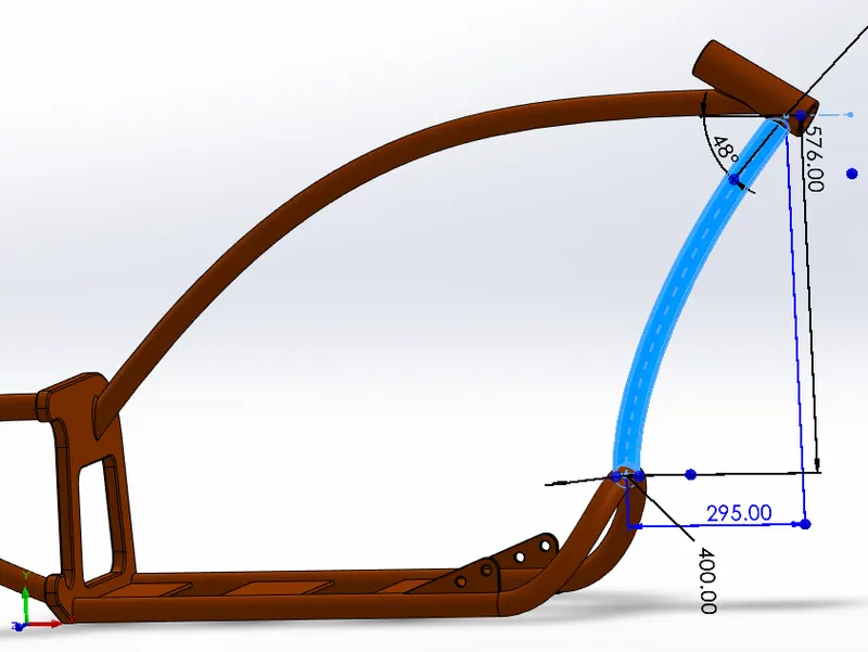
Here, Sweep command is shown in figure.
All the command and features used for creation of chassis is discussed in above parts.
(12) Engine :-
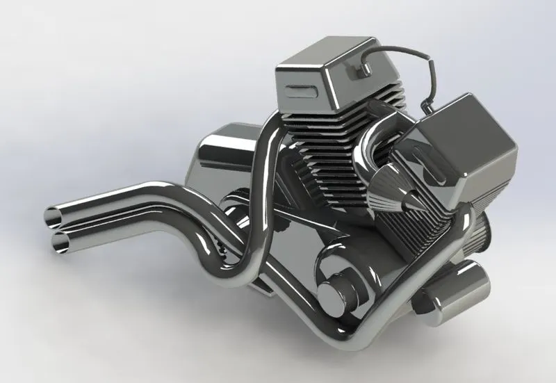
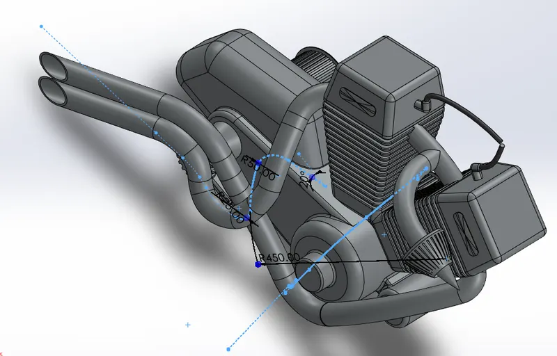
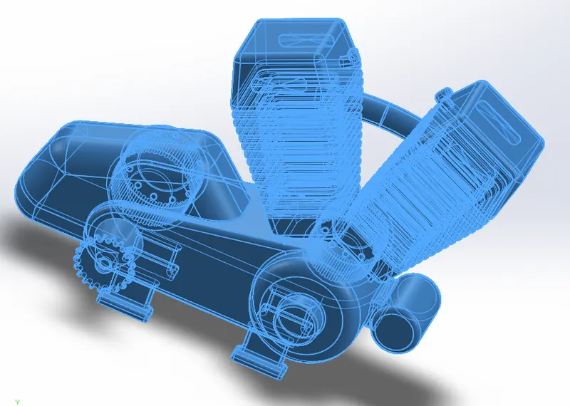
So, here the command used in creation of engine of american chopper model are:-
A. Composite Curve Command :- Composite curve command in solidwork is used to create composite curve by combining curve,sketches geometery and model edges into single curve.
B. Pierce Tool :- This tool in solidworks is used to snap a point of geometery to the another geometery in different plane.eg:- snaping the centre of any circle to the combine or projected curve.
Here, projected curve command and combine command is displayed in the figure.
Else, various other tools were used in creation of power house of the american chopper model which are discussed above in different parts of chopper model.
(13) Chain :-
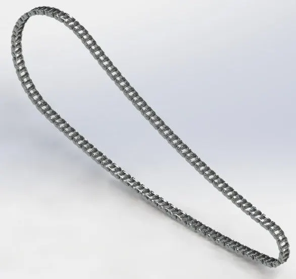
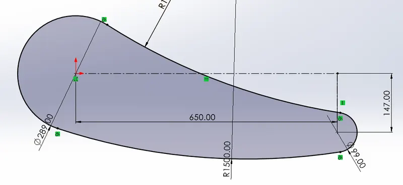
Arc,line,circle command are visible in the Figure.
All Commands used in designing chain of american chopper model are discussed in above all the parts of the model.
(14) Assembly of American Chopper :-
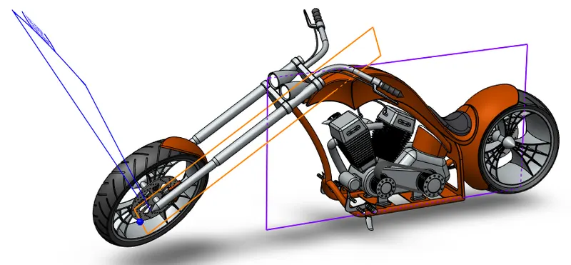
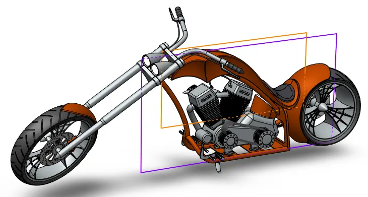
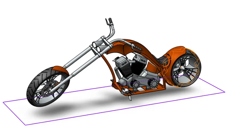
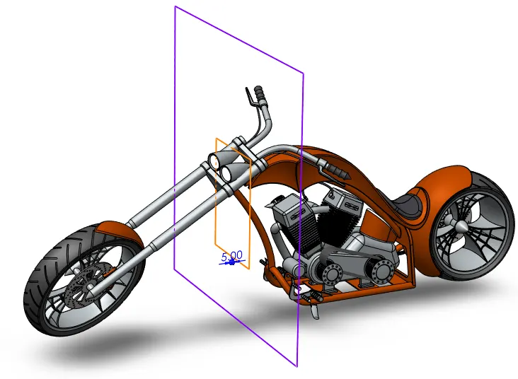
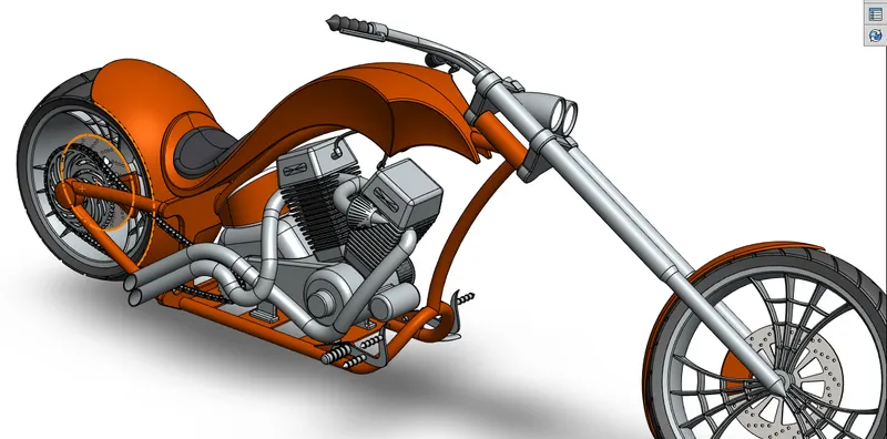
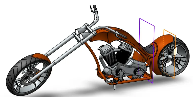
So, here the commands used in the assembly of american chopper model are :-
Mate's in the assembly in the solidworks is used for the proper alignment or parts togeather and planes in any direction. In this chopper model assembly various mate commands were used for alignment of parts to chassis to get the proper overview of the model.
A. Coincident Mate :- The coincident mate refers to bring two planar surfaces flush or aligned with each other or a surface, edge, or vertex in contact with each other.
B. Concentric Mate :- A concentric mate forces two cylindrical faces to become concentric. The faces can move along the common axis, but cannot be moved away from this axis.
C. Width Mate :- A width mate constrains a tab between two planar faces. Width references can include: Two parallel planar faces. Two non-parallel planar faces.
D. Limit Angle Mate :- The Limit Angle Mate is an advanced mate type that allows you to specify a range of angular values that a component is able to move.
E. Distance Mate :- A distance limit mate allows two surfaces or points to move along a single axis to a maximum and minimum distance. This limit looks a lot like a sliding motion when used.
F. Tangent Mate :- Tangent mates brings at least one cylindrical or curved face or edge in line with another face or edge.
G. Parallel Mate :-Parallel: Keeps selected items at a constant distance from each other.
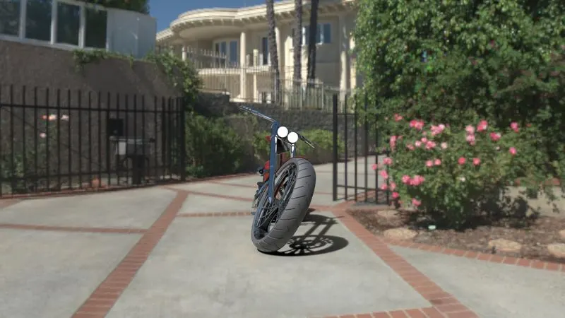
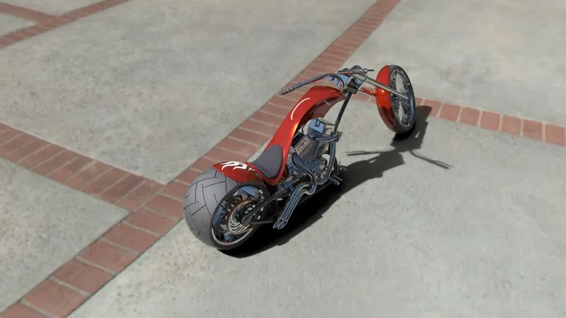
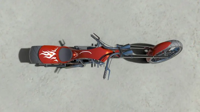
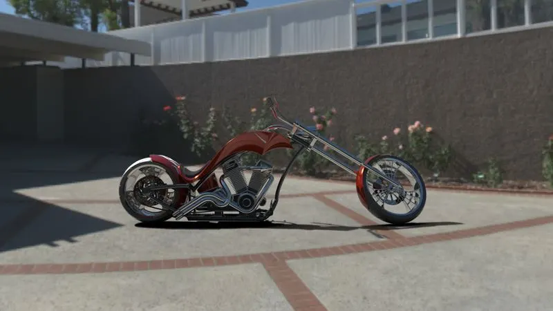
7. RENDERED IMAGES OF AMERICAN CHOPPER ASSEMBLY :-
(1) CAMERA VIEW :-
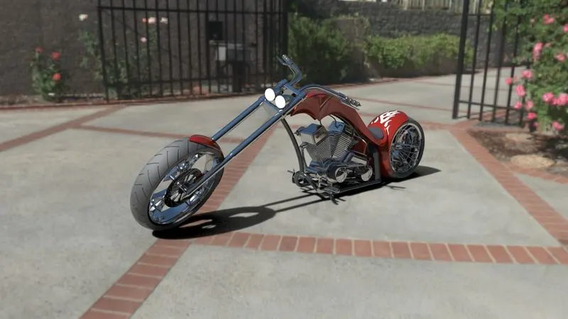
(2) SIDE VIEW :-
(3) ISOMETRIC VIEW :-
(4) TOP VIEW :-
(5) FRONT VIEW :-
8. CONCLUSION
(1) A model has been developed with the help of Solidworks by using some global variables, dimension
and equation.
(2) The users can update model just by changing ground clearance, Tire size, etc.
(3) In this way designer can perform tasks especially in the mechanical design.
(4) After this user are comfortable to design and modify different components