Wiring harness design in CATIA V5 - 3D modeling Week 2 Challenge
WEEK 2 CHALLENGE
WIRING HARNESS DESIGN IN CATIA V5 - 3D MODELLING
AIM: - Download following connectors & Connector clip cad data from given link & define it as Electrical Connector using Electrical Part design Workbench. Define all the necessary properties to Connectors & Clip.
- Deutsch DT06 – 08SA ( https://www.te.com/usa-en/product-DT06-08SA.html)
- Tyco 174357-2 (https://www.te.com/usa-en/product-2-174357-2.html?source=header-match)
- Tyco 85229-1 – (https://www.te.com/usa-en/product-85229-1.html?q=85229&source=header)
TERMINOLOGIES AND DEFINITIONS
REPORT
- As suggested components had been downloaded from corresponding websites and stored as input features for the challenge.
- Created geometrical parameter to all the three parts i.e, Deutsch DT06 – 08SA, Tyco 174357-2, Tyco 85229-1
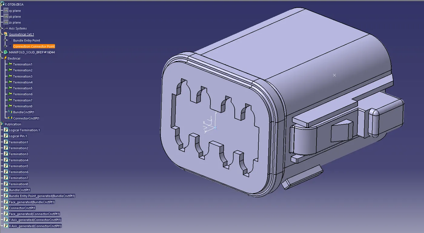
- Deutsch DT06 – 08SA
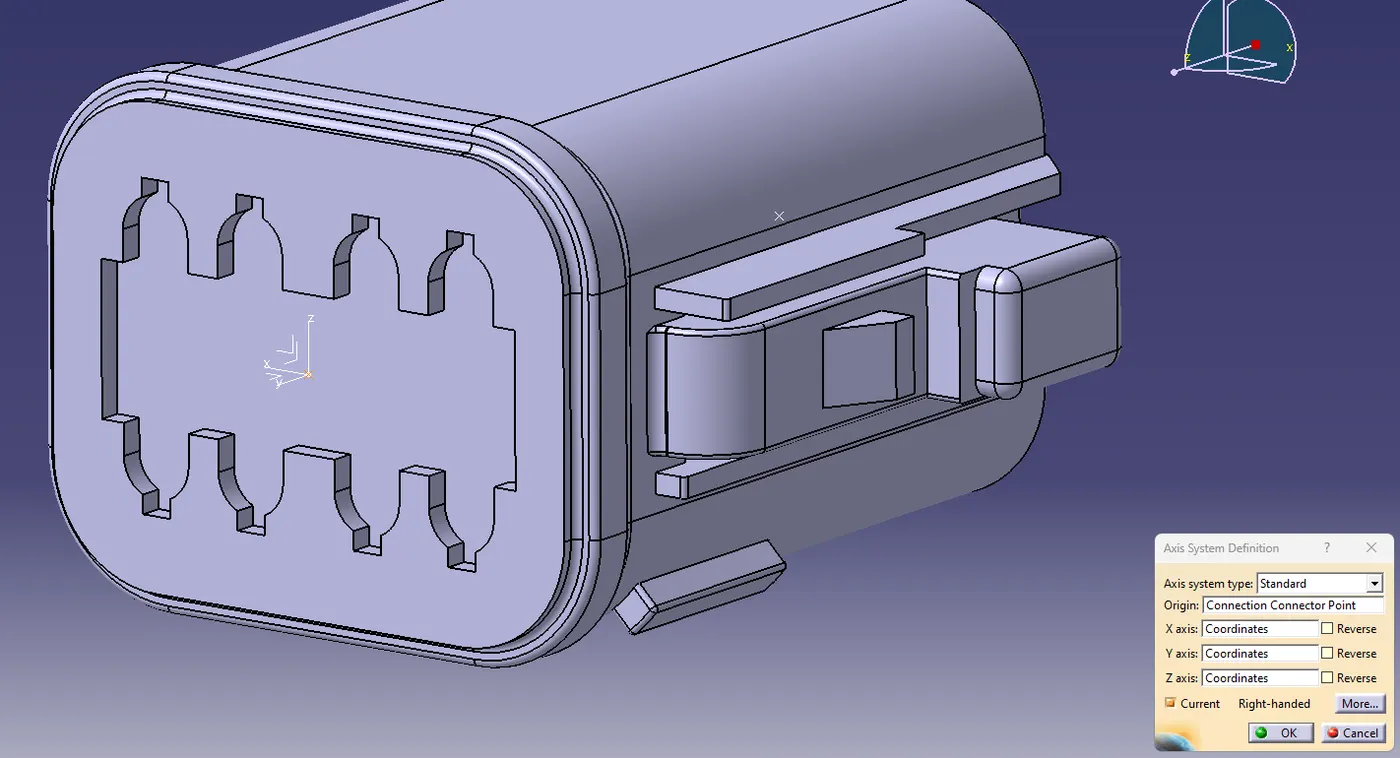
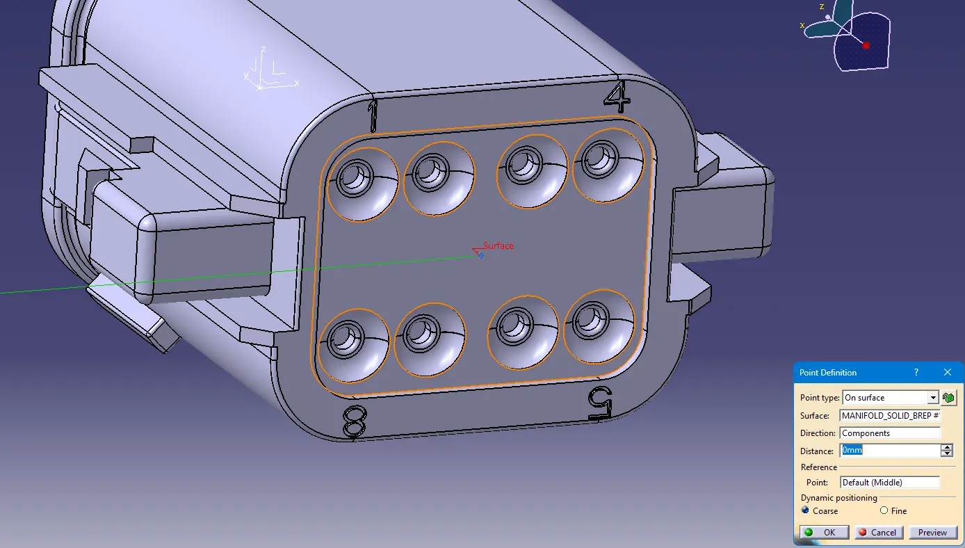
- Create midpoint on the contact face which will be normal to bundle insertion
- Create Axis system wih respect to the point which we have created and defining the axis direction in Part Workbench
-
Switch to 'Electric Part Design' and define the part as connector in Catia V5, give no. of termination as 8 because we have 8 entry points for wire.
- Define the connector and bundle connection point
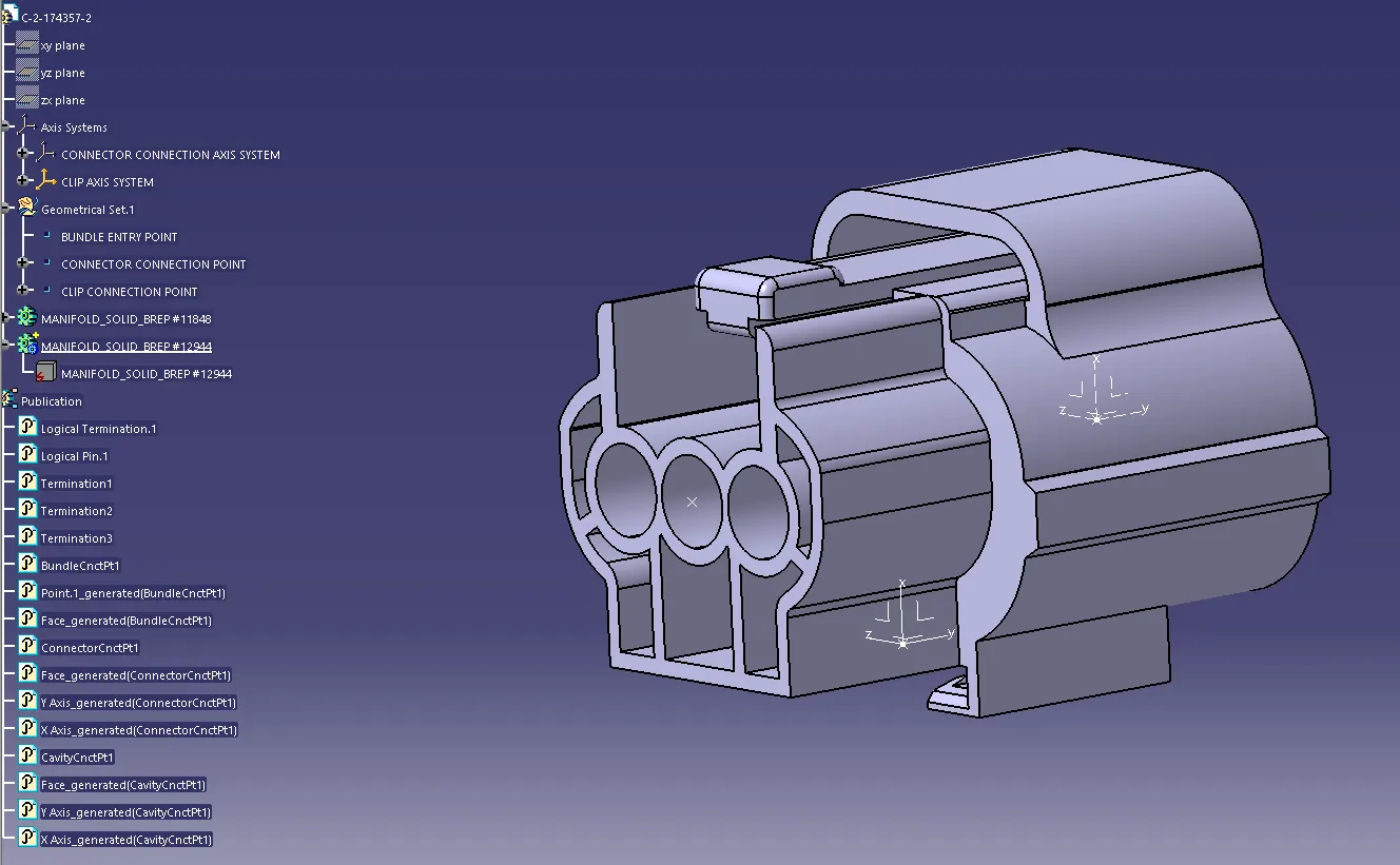
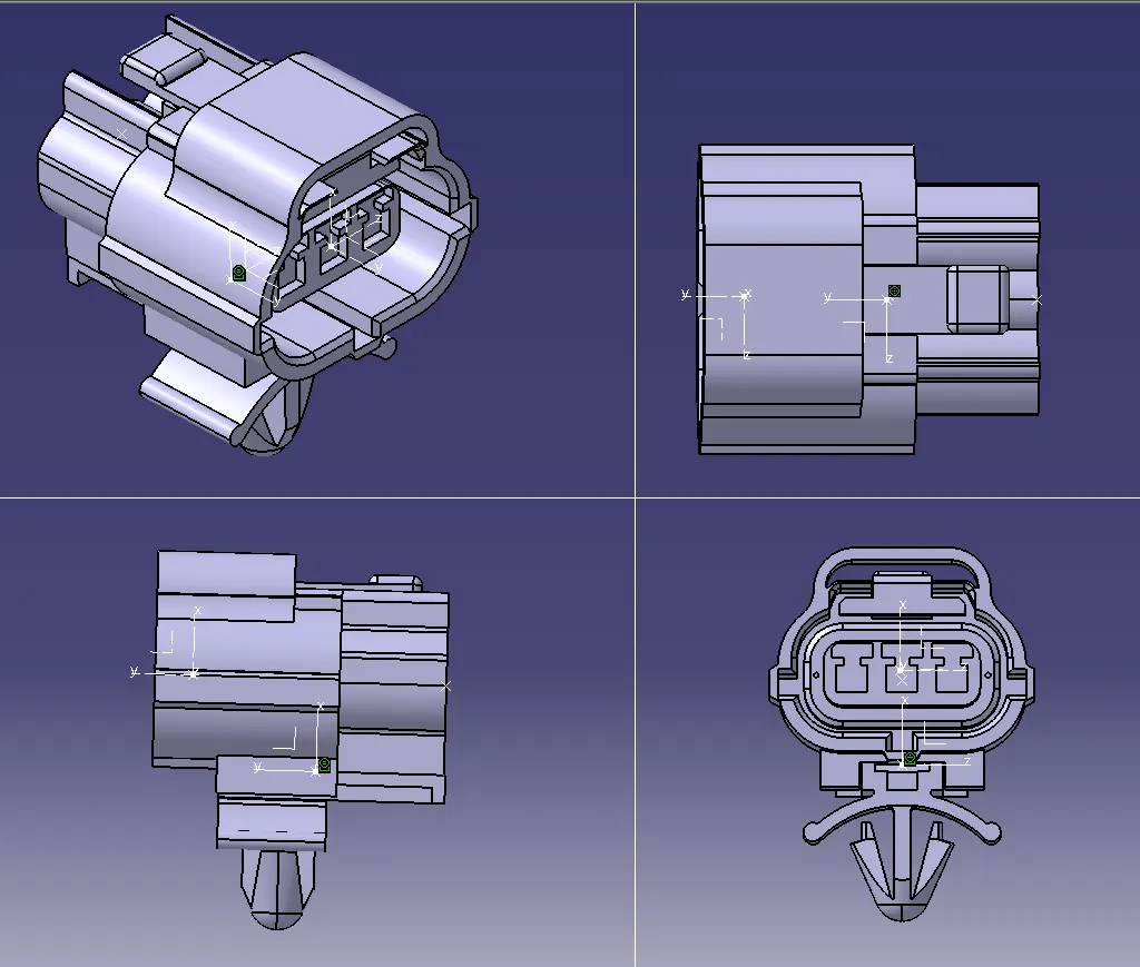
- Tyco 174357-2
- Create midpoint on the contact face which will be normal to bundle insertion
- Create Connector connection point
- Create Connector connection axis system
- Create cavity connection point
- Create cavity connection axis system
- Switch to Electric part design and define part as connector
- Define Connector connection point and cavity connection point
- For Tyco 85229-1,
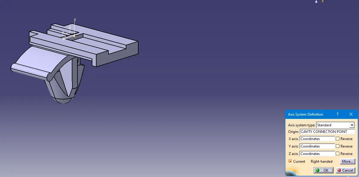
- Create midpoint on the face which is goint to mate with a connector
- create cavity connection point
- create cavity connection axis system and orientation should be same as in connector
- Switch to Electric part design and define part as Mounting Equipment
- Define cavity connection point
- Commands used for defining the geometrical entities are given below.
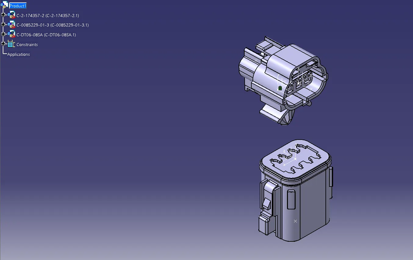
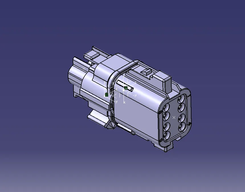
- Slendering to Electrical Assemby design workbech the components are assembled as what it is used for.
- Catalogue has been created Electrical Identity used to define and store electrical components for future reference and is attatched along with the product file.
CONNECTOR DEFINITIONS
1. Deutsch DT06-08SA
 |
 |
2. Tyco 74357-2
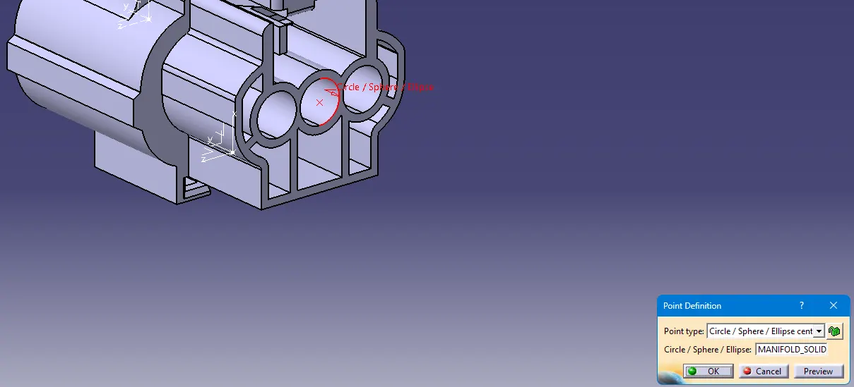 |
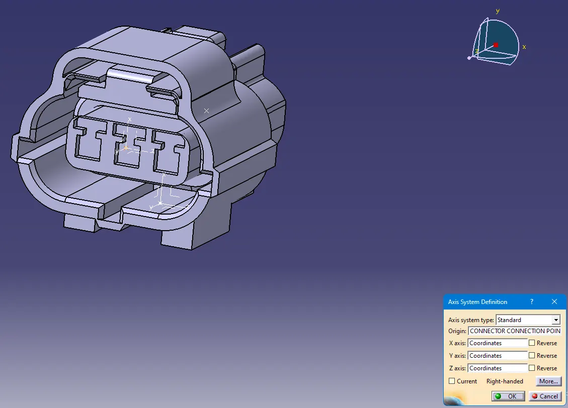 |
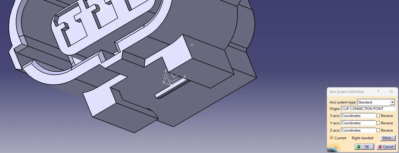
3. CLIP (Tyco 85229 -1)
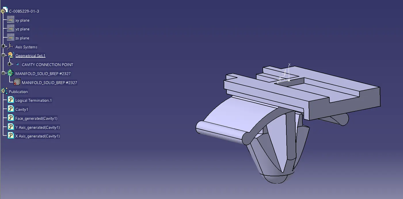
ASSEMBLY
 |
 |
COMMANDS USED
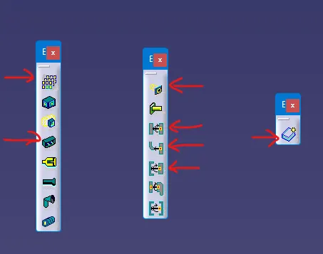 |
ELECTRICAL PART WORKBENCH COMMANDS 1. Define Mounting Equipment 2. Define Connector 3. Define Cavity 4. Define Connector Connection Point 5. Define Bundle Connection Point 6. Define Cavity Connection Point 7. Store Device for Catalogue creation. |
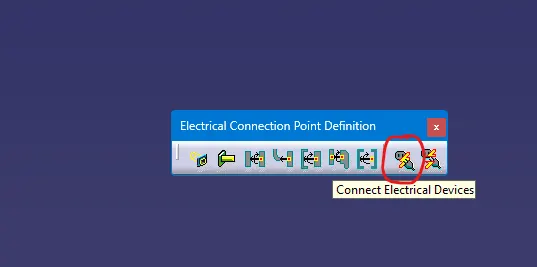 |
ELECTRICAL ASSEMBLY DESIGN CONSTRAINTS 1. Connect Electrical Devices |
NOTE: -
- Defined Electrical Connector using Electrical Part design Workbench.
- Defined necessary properties to Connectors & Clip with points and axis systems using Electrical Part design Workbench and aligned using Electrical Assembly Design.
- Individual parts and assembly files are attatched in the below file upload tool bar.