Wiring harness design in CATIA V5 - 3D modeling Week 2 Challenge
AIM: Using connectors & Connector clip cad data from the given link & define it as Electrical Connector using the Electrical Part Design Workbench. Define all the necessary properties of Connectors & clips.
CONNECTORS
Wire harnesses provide both protection and organization for a cable assembly. Outside forces like abrasion, extreme temperatures, moisture, dust, and more, all bombard a cable assembly and can work to degrade components over time. Wire harnesses provide protection against these forces and are specifically engineered for whatever environment the application happens to be. Wire harness connectors, as part of this system, are the bridge for providing a consistent flow of data, signal, or power.
There are essentially two main types of wire or cable harness connectors—male and female. Male and female wire harness connectors serve to provide the necessary junctions between the many different elements of the wire harness to produce an efficient transmission of data, signal, or power through the system. In simplistic terms, plugs are usually male connectors and jacks are female wire harness connectors.
Connectors come in all sorts of sizes, shapes, and dimensions in order to fit perfectly within the electrical system they need to support. From cutting edge medical devices to complex industrial control systems, the humble wire harness connector makes these marvels of modern technology possible.
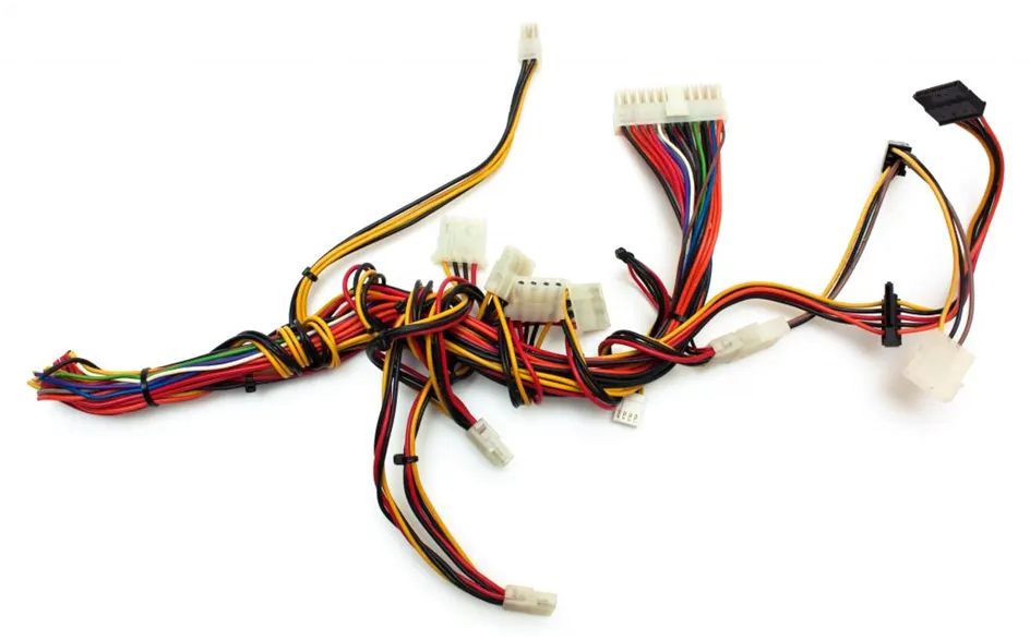
CONNECTORS USED:
DEUTSCH DT
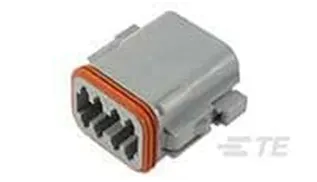
PART NAME: DT06-08SA
Internal Description: PLG, 8P, GRY, N, A
Connector & Housing Type: Housing for Female Terminals
Mating Pin Diameter: 1.59 mm
Connector System: Wire-to-Wire
Number of Positions: 8
Tyco 174357-2
AMP Econoseal, Econoseal J - 070
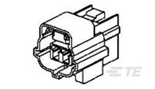
PART NAME: 2-174357-2
Internal Description: 070 EJ-2(2) PLUG ASSY 3P SIR
Connector & Housing Type: Housing for Female Terminals
Mating Tab Width: 1.8 mm
Connector System: Wire-to-Wire
Number of Positions: 3
CONNECTOR MOUNTING CLIP
Mounting Clips are used for supporting conduits. These clips are made of High Quality Impact Resistant Polyamide. The mounting clips are stackable and are fixed with the help of screws on to the panel or equipment surface.
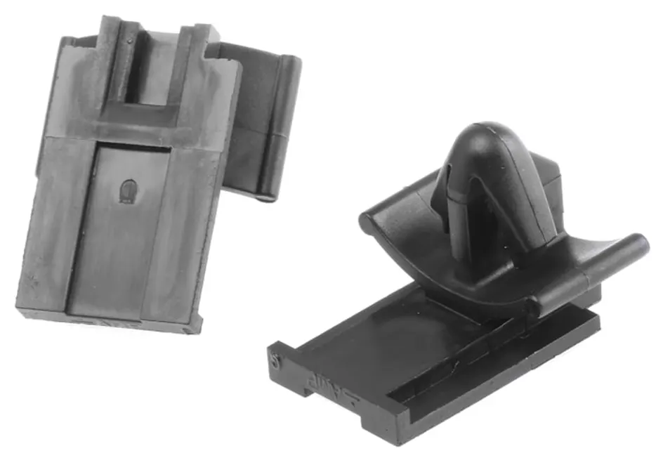
Tyco 85229-1
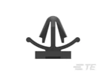
Econoseal
Internal Description: CLIP HSG FOR 070 (EJ MK-II)
Automotive Connector Accessory Type: Mounting Clip
Primary Product Material: Poly Amide
Primary Product Color: Black
<!-- [if !supportLists]-->1. <!--[endif]-->Deutsch DT06-08SA
i. Mechanical Part Design Workbench
Defining geometrical properties (points and axis system)
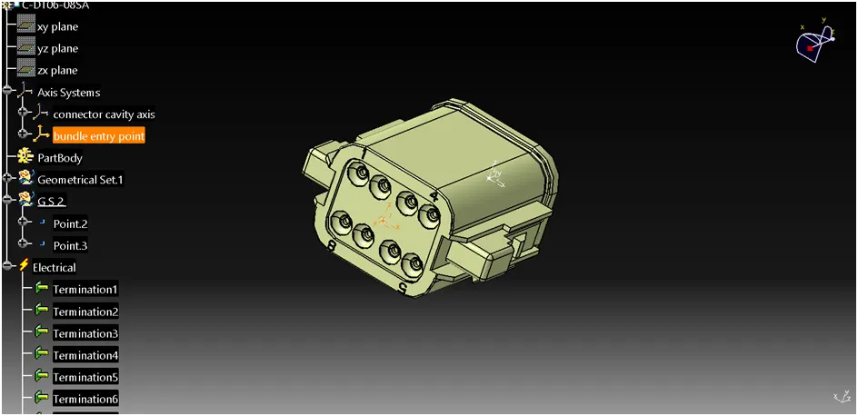
Bundle entry side center point - Selecting two random points diagonally to get a center point, under point type between. Place the axis on the centre point.
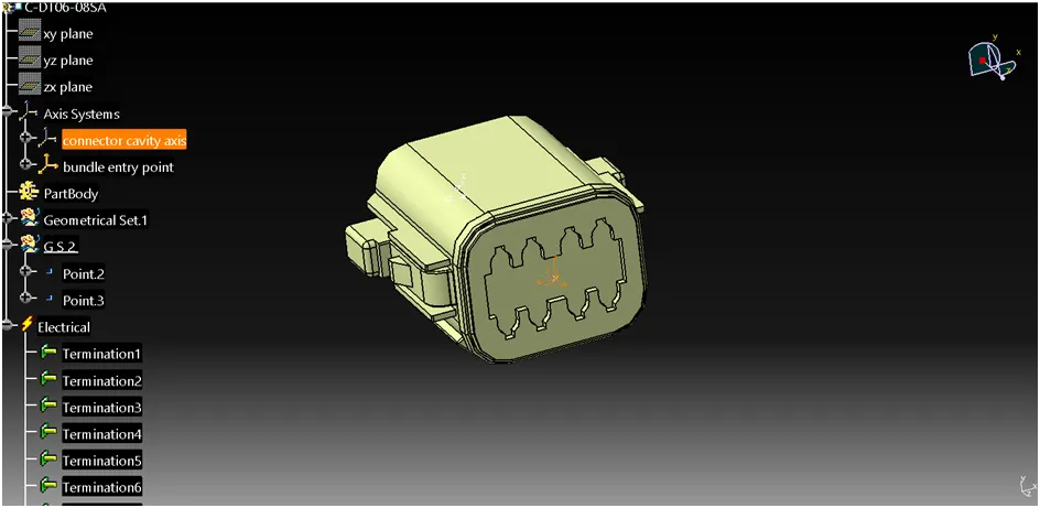
Mating side axis system - Creating an axis system concerning the centre point as the origin of the axis. The Y axis is directed at the mating direction, the X axis is directed towards the locking side and the Z axis is directed upwards.
ii. Electrical Part Design Workbench
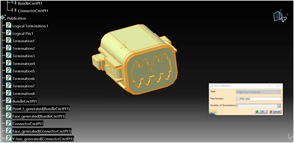
Define part as a connector
Defining part as an electrical connector under Electrical Part Design Workbench. Selecting the number of terminations 8.
Define bundle connection point (bundle/wire entry side)
Defining bundle connection point at the bundle entry side where, representation is the face, point as the center point, and initial condition also as the face.
<!-- [if gte vml 1]>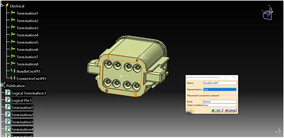 <!--[endif]-->
Define connector connection point (mating side)
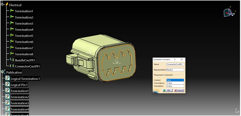
Defining connector connection point at the mating side of the connector where representation is the center point, contact is the face, coincidence is the Y axis, and, orientation is the X axis.
2. Tyco 174357-2
i. Mechanical Part Design Workbench- Defining geometrical properties (points and axis system)
Bundle entry side center point - Selecting two random points diagonally to get a center point, under point type circle/sphere/ellipse center.
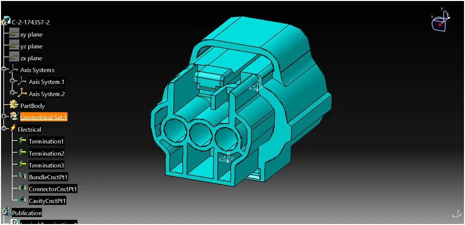
Mating side centre point – Selecting two random points diagonally to get a centre point, under point type between.
Mating side axis system - Creating an axis system concerning the centre point as the origin of the axis. The Y axis is directed at the mating direction, the X axis is directed upwards and the Z axis is directed to the side.
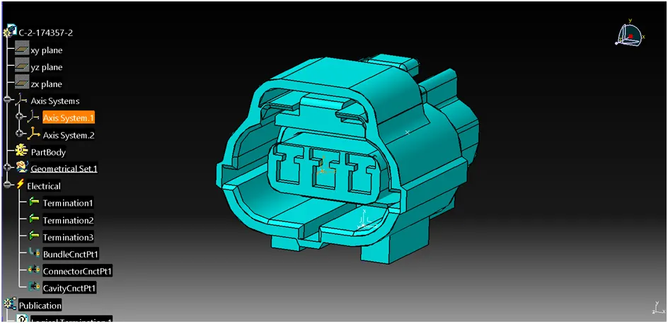
Centre point for cavity connection - Selecting the edge of the cavity connection part to get a centre point, under point type on the curve.
Axis system for cavity connection - Creating an axis system concerning the centre point as the origin of the axis. The Y axis is directed at the connection direction, the X axis is directed upwards and the Z axis is directed to the side.
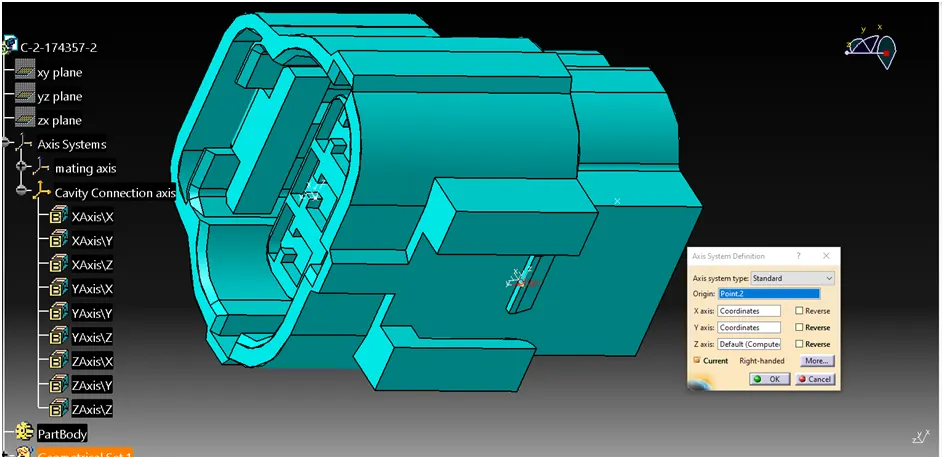
ii. Electrical Part Design Workbench
Define part as a connector- Defining part as an electrical connector under Electrical Part Design Workbench. Selecting the number terminations 3.
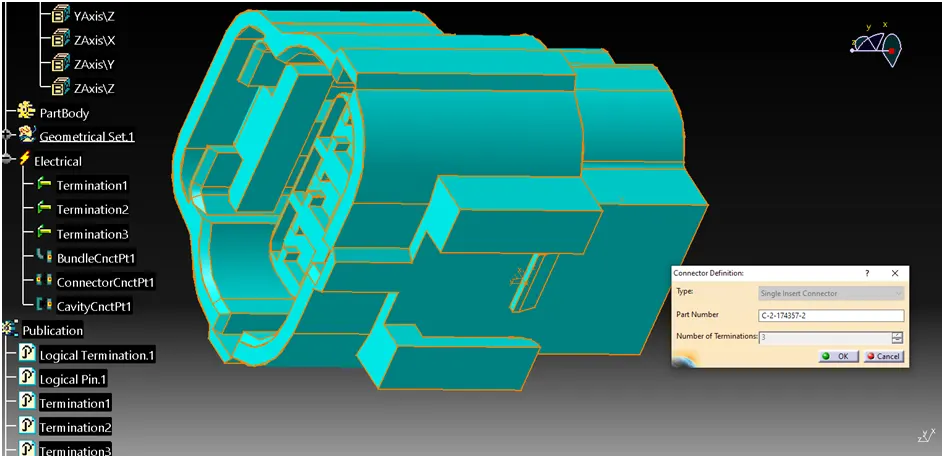
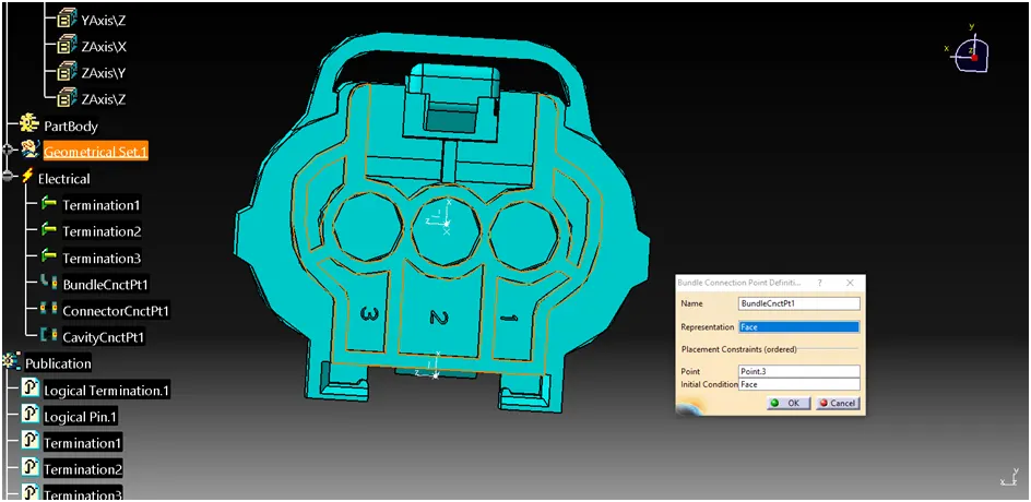
Define bundle connection point (bundle/wire entry side)
Defining bundle connection point at the bundle entry side where, representation is the face, point as the center point, and initial condition also as the face.
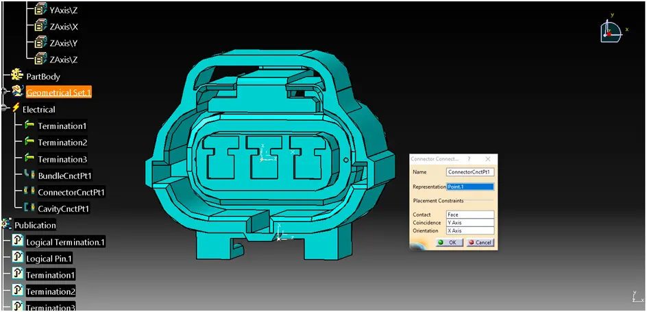
Define connector connection point (mating side)
Defining connector connection point at the mating side of the connector where representation is the center point, contact is the face, coincidence is the Y axis, and, orientation is the X axis.
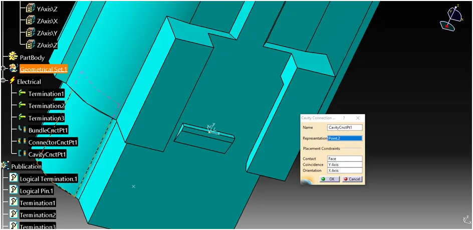
Define cavity connection point (optional, if connector needs mounting clip)
A cavity connection is defined as the connecting part for a connector clip where representation is the center point of the cavity connection, contact is the connection face, coincidence is the Y axis and, orientation is the X axis.
3. Tyco 85229-1 (Mounting Clip)
i. Mechanical Part Design Workbench
Defining geometrical properties (points and axis system)
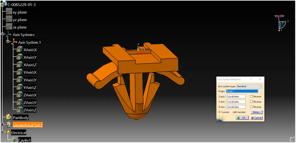
Mounting clip center point -Selecting the edge of the connecting part to get a center point, under point type curve.
Mounting clip axis system - Creating an axis system for the cavity, the origin is the center point, the Y axis is directed towards the insertion, the X axis is directed upwards and, the Z axis is directed to the side. The axis direction should follow the connector's cavity connection axis direction for proper mounting.
ii. Electrical Part Design Workbench
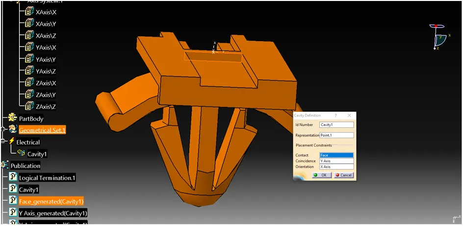
Define part as a Mounting Equipment
The clip is defined as electrical mounting equipment.
Defining cavity - A connector clip is defined as the cavity where representation is the center point, contact is the face of the connecting part, coincidence is the Y axis and, orientation is the X axis.
iii. Electrical Assembly Design Workbench
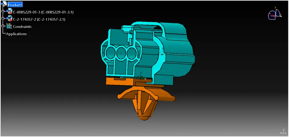
Connect Electrical Devices
The connector and connector clip are connected under the electrical assembly design workbench using connected electrical devices.
CONCLUSION
In this challenge I have gained knowledge about connectors and clips. By using electrical workbench in Catia v5 learnt the assembly design of mating electrical parts.