Wiring harness design in CATIA V5 - 3D modeling Week 2 Challenge
AIM
Download following connectors & Connector clip cad data from given link & define it as Electrical Connector using Electrical Part design Workbench. Define all the necessary properties to Connectors & Clip.
CONNECTORS
1.Deutsch DT06 – 08SA
Specifications
- Connector & Housing Type : Housing for Female Terminals
- Mating Pin Diameter : 1.59 mm [ .063 in ]
- Connector System : Wire-to-Wire
Number of Positions : 8
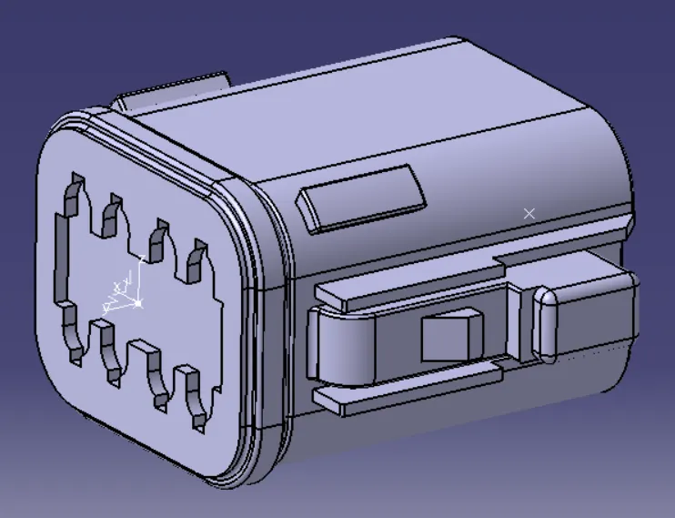
first work on the part design workbench to create bundle connection point, connector connection point and connector connection axis for the given connector .
The axis system for the connector connection created like ,y axis pointing towards the front face of the connector ,X axis pointing in the direction towards the locking mechanism and Z axis pointing across the
connector from left or right .
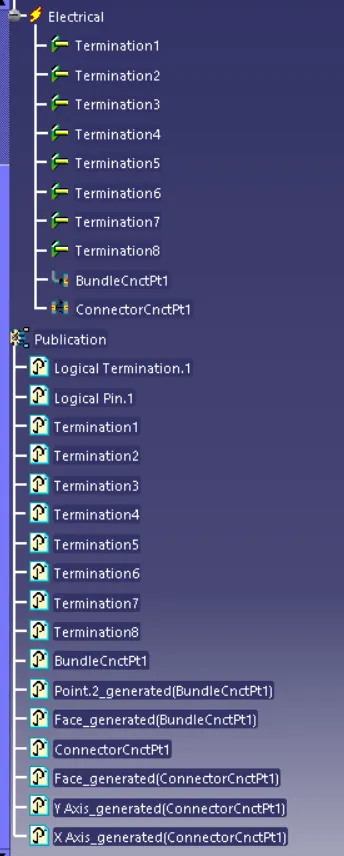
Next go to electrical part design workbench and define it as a connector with 8 termination points .Then define bundle connection point and connector connection point in electrical part design workbench.
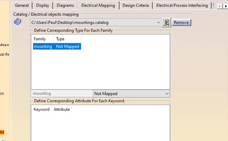
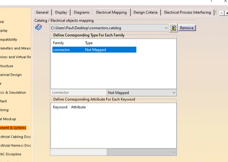
then create a cataloge in the catalog document workbench add a electrical type connector family then save the catalogedocument and return to electrical part workbench,store the device using the cataloge in connector family .
2.Tyco 174357-2
- Connector & Housing Type : Housing for Female Terminals
- Mating Tab Width : 1.8 mm [ .071 in ]
- Connector System : Wire-to-Wire
- Number of Positions : 3
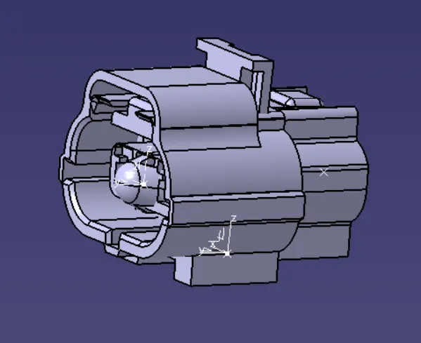
first work on the part design workbench to create bundle connection point, connector connection point,cavity connection point , connector connection axis and cavity connection axis for the given connector .
Axis system should be in the same direction .
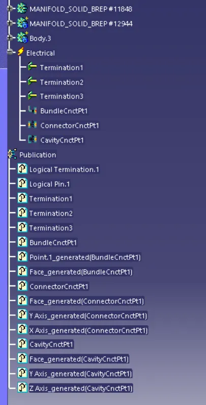
Next use electrical part design workbench and define it as a connector with 3 termination points .Then define bundle connection point , connector connection point and cavity connection point in electrical part design workbench.
Then use store device option in electrical part design workbench and select the created connector catalogdocument to store the data.
- MOUNTING CLIP
Specifications
Automotive Connector Accessory Type : Mounting Clip
Primary Product Material : PA
Primary Product Color : Black
Operating Temperature Range : -40 – 120 °C [ -40 – 248 °F ]
The below fig. shows the downloaded cad file of Mounting Clip
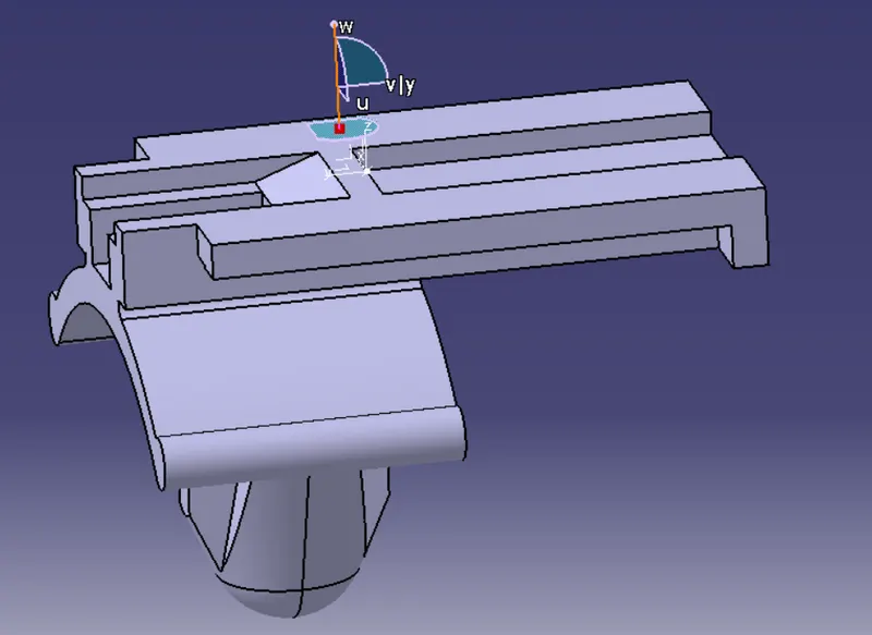
In the part design workbench create the connector connection point and connector connection axis for the mounting clip.Centre of mating face edge is taken as connector connection point.The axis system of connector and mounting clip should be in same direction .
Then switch to electrical part design workbench and define it as a cavity.
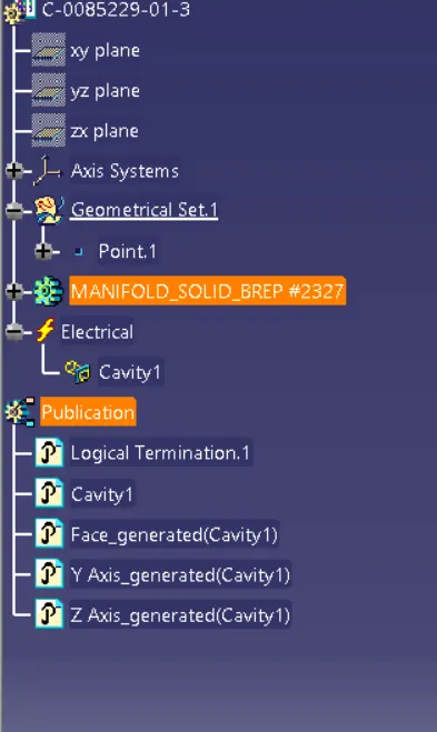
For assemble the connector and mounting clip switch to electrical assembly design workbench and use connect electrical device option.it create all the required constrains for the assembly.
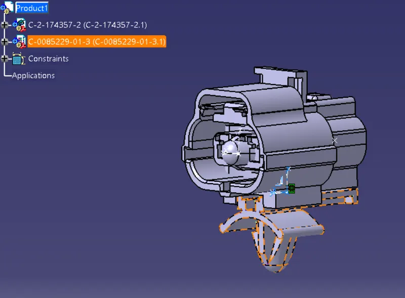
For assemble the connector and mounting clip switch to electrical assembly design workbench and use connect electrical device option.it create all the required constrains for the assembly.