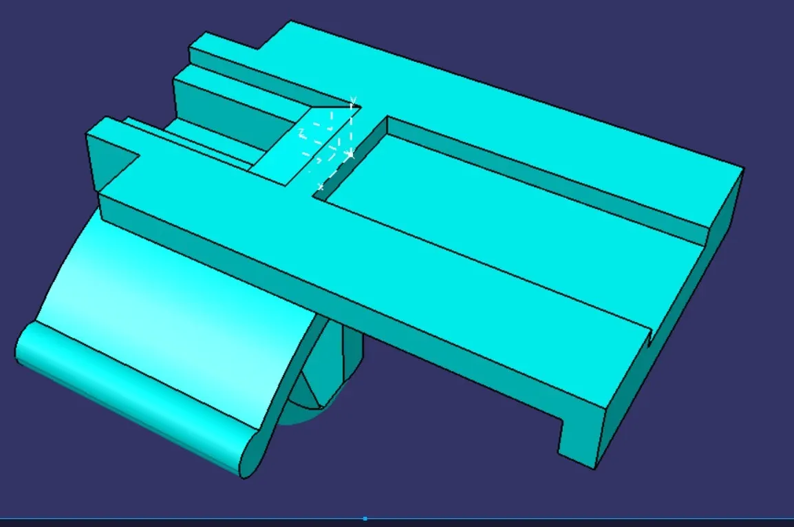
Wiring harness design in CATIA V5 - 3D modeling Week 2 Challenge
1. Deutsch DT06 – 08SA
- Create an axis system so that the mounting or inserting features entry and exit orientation with assembly contact conditions can be handled according to the need.
- Define the Connector as an electrical component and include 8 terminals, because this is a connector, not mounting.
- To insert the wire into the connector via terminals, we define the bundle connection point on the side of the terminal face to its contact and orientation.
- To insert this connector into another connector and cavity, we define the connector connection point from the front face to its contact and orientation.
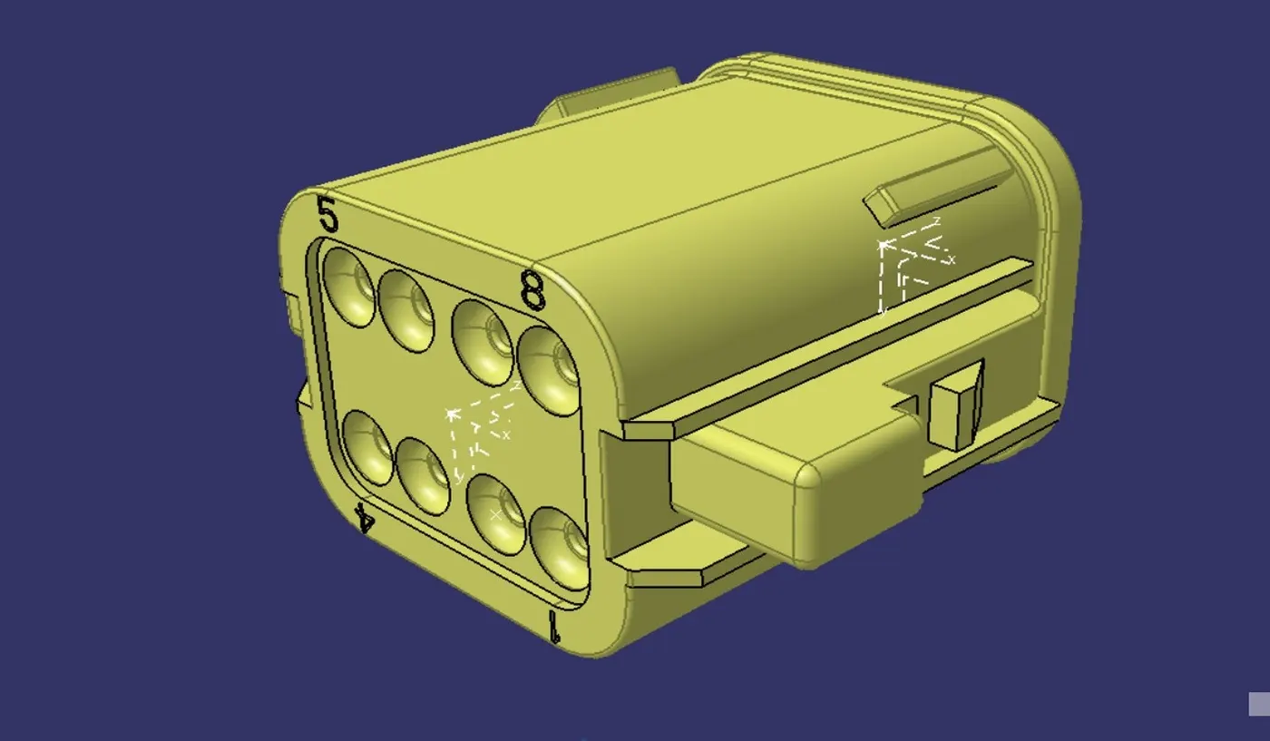
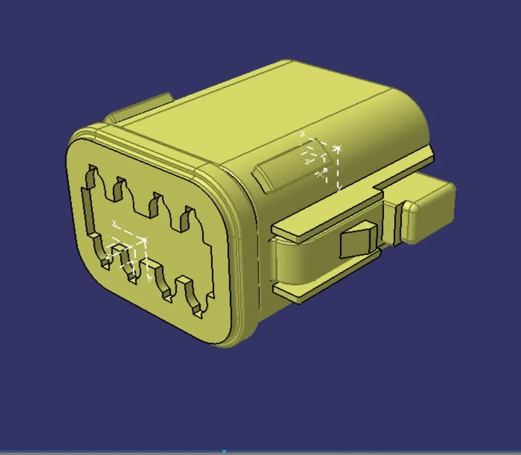
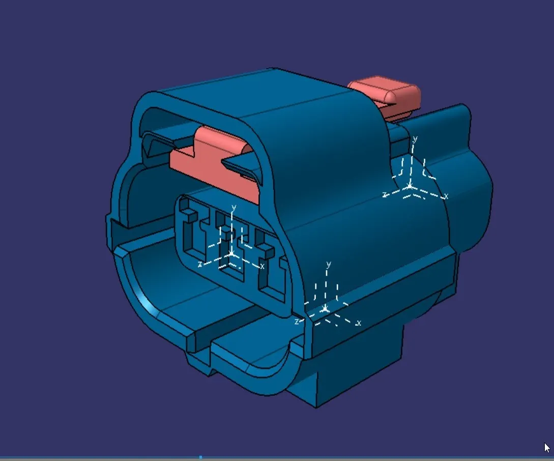
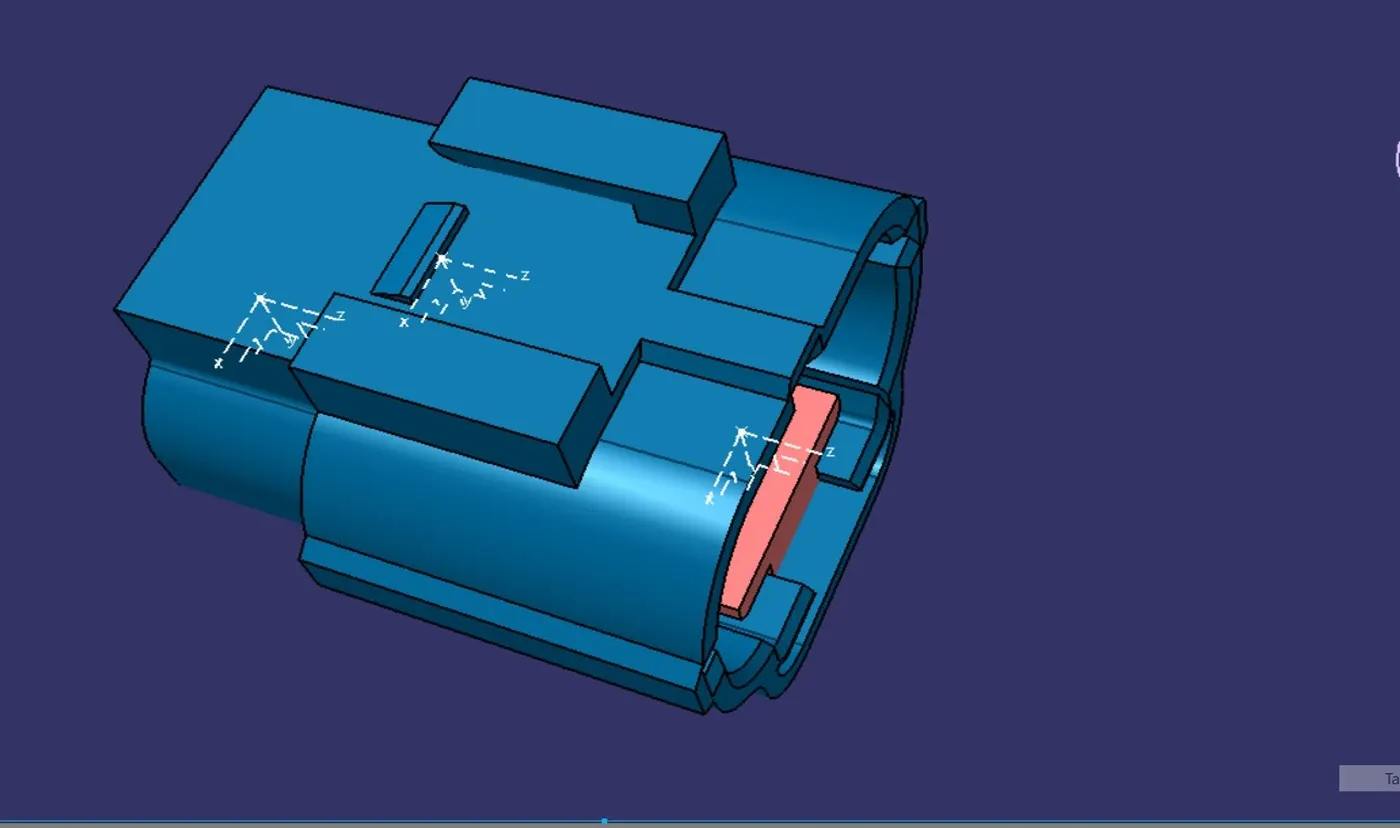
2. Tyco 174357-2
- Create an axis system so that the mounting or inserting features entry and exit orientation with assembly contact conditions can be handled according to the need.
- Define the Connector as an electrical component and include 3 terminals, because this is a connector.
- To insert the wire into the connector via terminals, we define the bundle connection point on the side of the terminal face to its contact and orientation.
- To insert this connector into another connector and cavity, we define the connector connection point from the front face to its contact and orientation.
- To mount this connector on the clip, we define the cavity connection point from the bottom face to its contact and orientation.
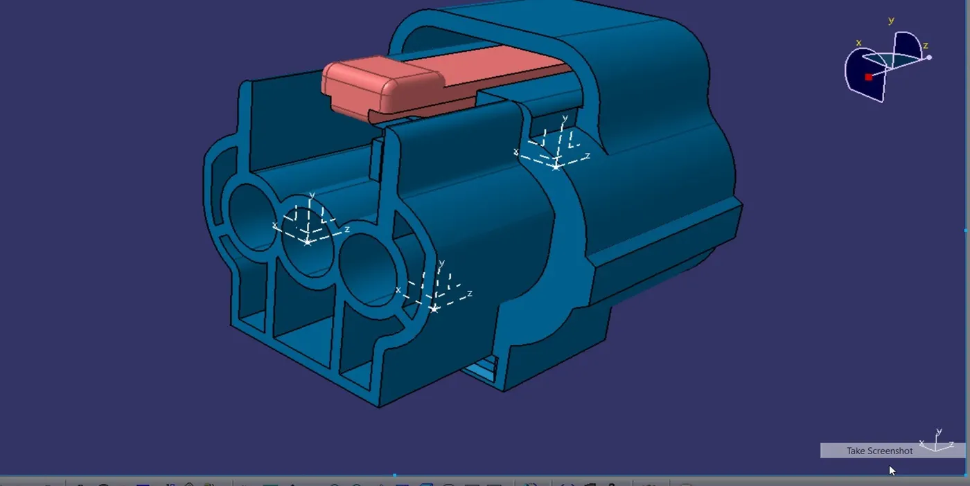
3. Tyco 85229-1
- Create an axis system so that the mounting or inserting features entry and exit orientation with assembly contact conditions can be handled according to the need.
- Define the Clip as mounting equipment, because this is a clip and mounts the parts.
- To insert mounting equipment, we define the clip as a cavity on the mating side of the face to its contact and orientation which can direct contact with the mounting parts.