Wiring harness design in CATIA V5 - 3D modeling Week 2 Challenge
WIRING HARNESS DESIGN :
AIM:
The objective of this project is to explore various connector and connector clip models and convert them into electrical components using CATIA V5 tool. This involves defining essential properties and comprehending the wiring harness design process by creating necessary provisions for assembly in the workbench.
Wiring Harness:
A wiring harness, also known as a cable harness or wiring assembly, is a methodical arrangement of cables within an insulated material. Its purpose is to transmit signals or electrical power. Cables are bundled together using straps, ties, lacing, sleeves, tape, conduit, or a combination thereof. This integrated wiring simplifies connections to larger components by incorporating the wiring into a single unit for effortless installation. The harness comprises various connectors such as terminals and wires running throughout the vehicle, transmitting essential information.
The wire harness design process is tailored to the geometry and electrical requirements of the equipment in which it is installed. After establishing the initial design, a schematic was created to create the manufacturing documents and assembly board for the channel.
Procedure for electrical connector definition:
- Deutsch DT06 – 08SA
- Tyco 174357-2
- Tyco 85229-1
1. Connector [Deutsch DT06 – 08SA]
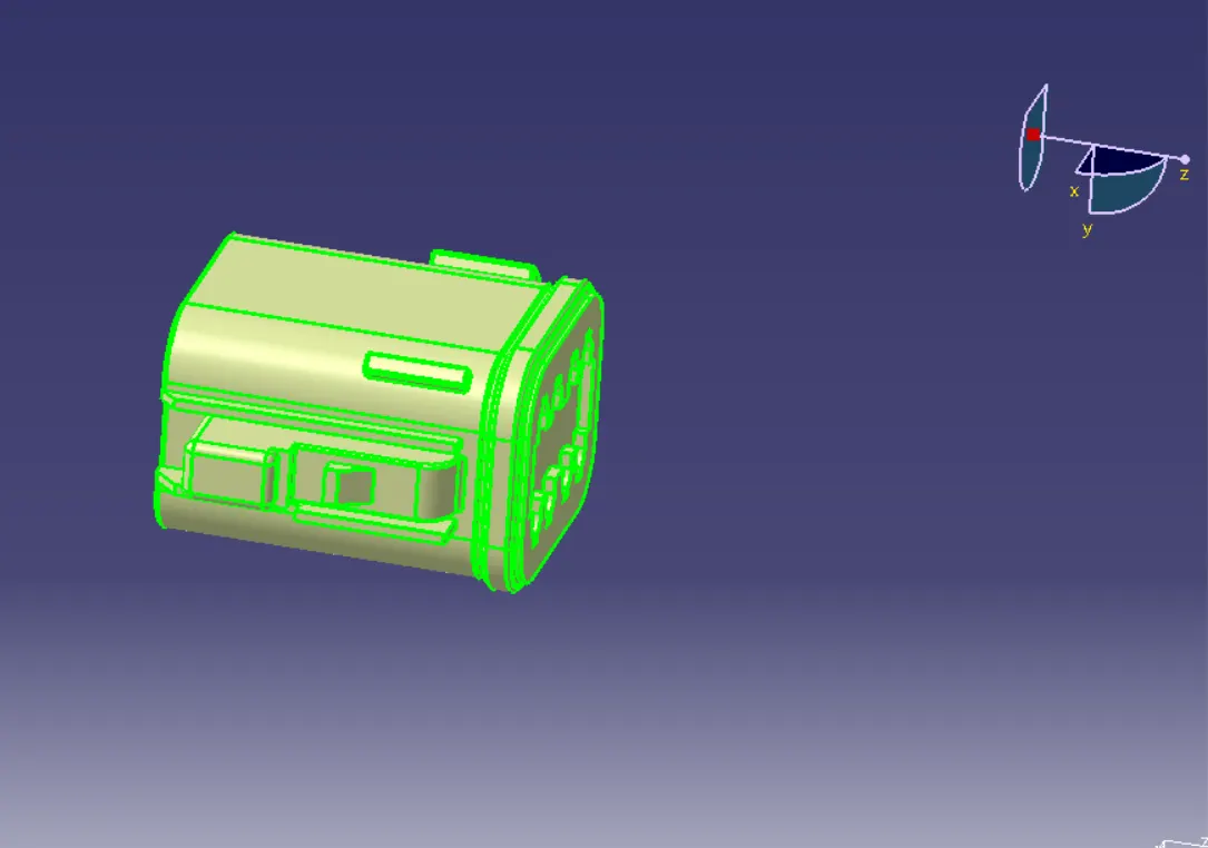
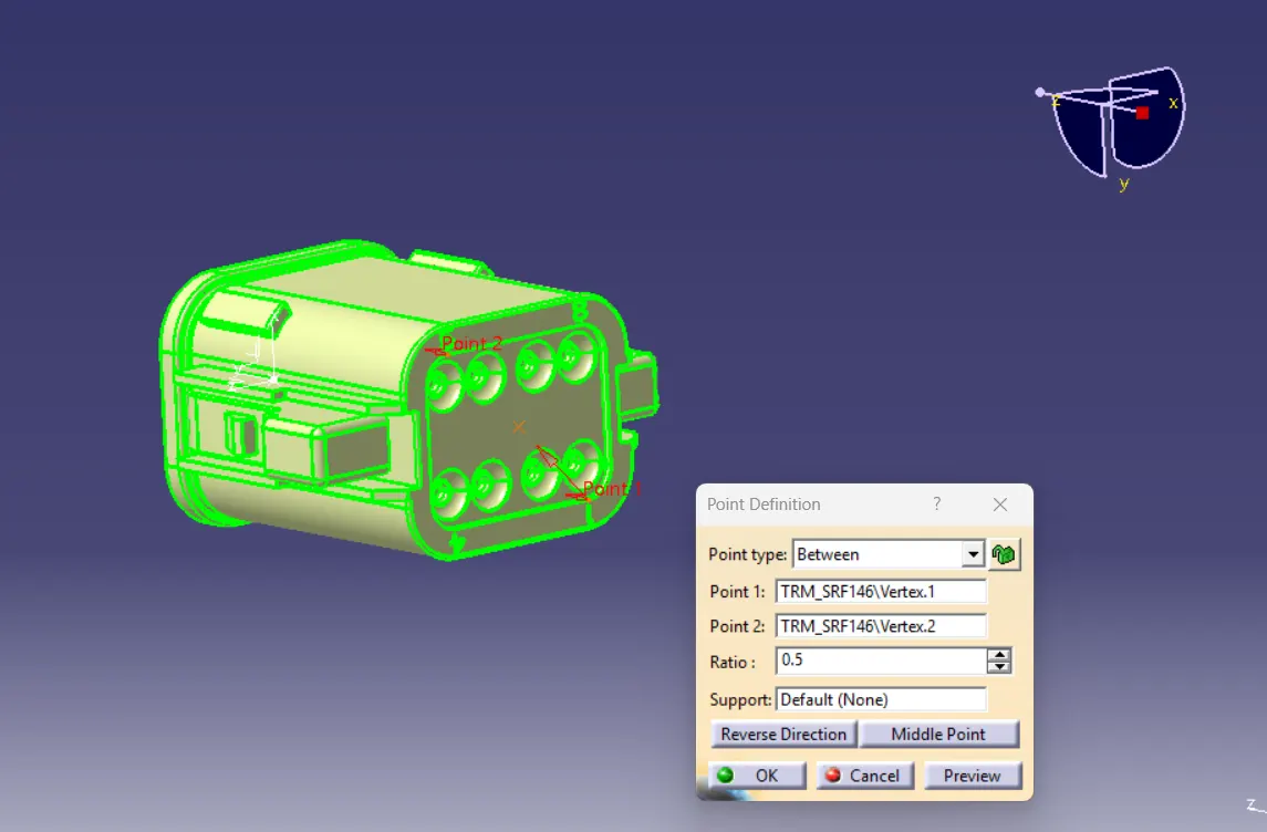
Meting side connector connection point:
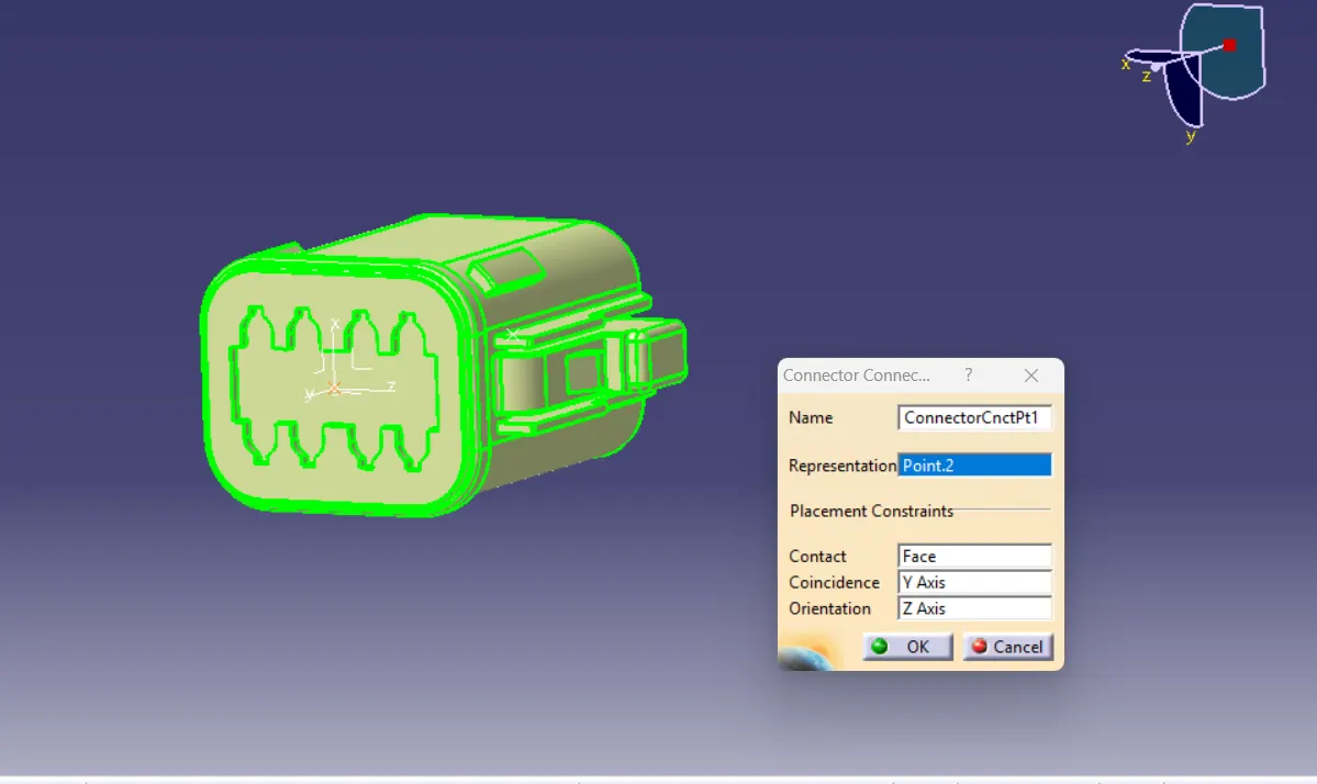
Locate the centre point of the connector by selecting two points on the outer edge of the connector mating area. Position the axis of the connector attachment point with respect to the centre point by placing the Y axis towards the direction of the attachment point (Mating point) and the X axis pointing to the side of the locking mechanism.
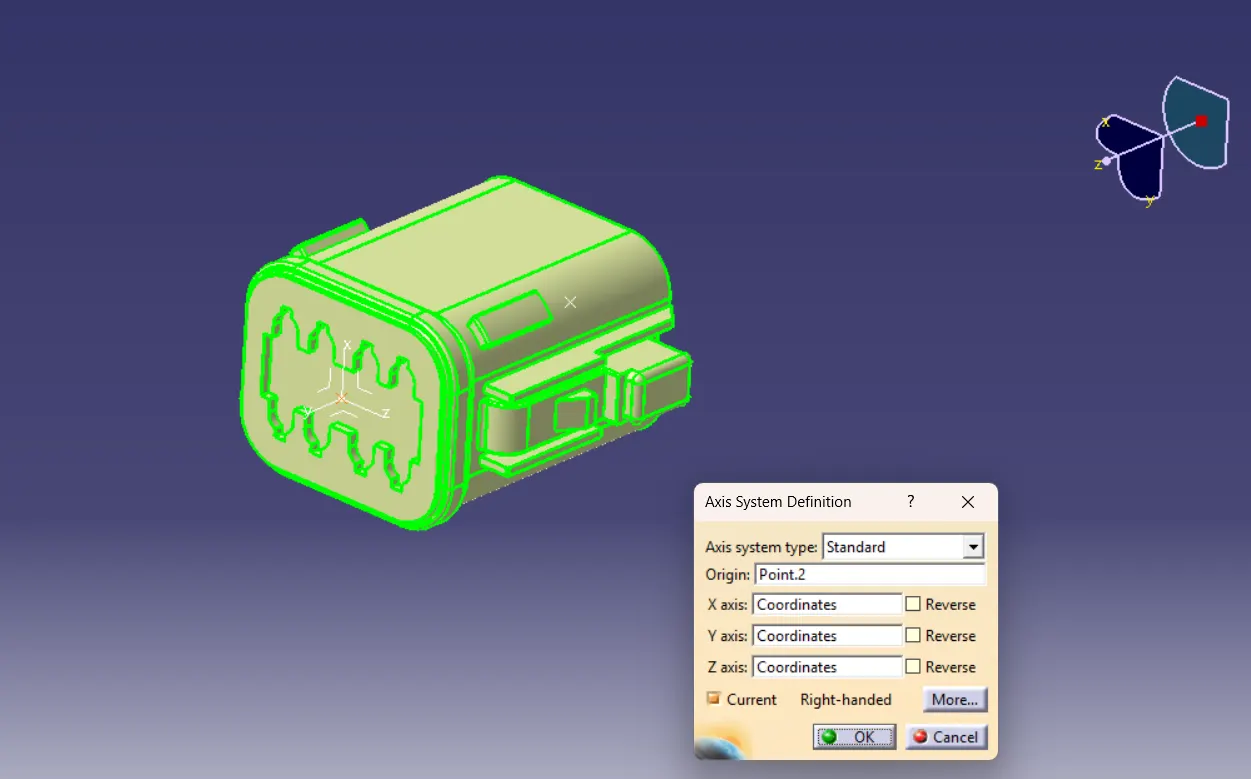
Bundle side connector connection point:
Create a midpoint on the wire entry side of the connector using the Point command.
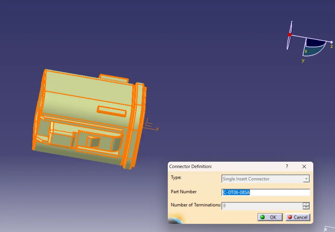
Then switch to electrical design, define the part as a connector and give the number of terminations.
By using the define bundle connection point command available in the electrical part design workbench and by selecting the face of bundle entry side and the created bundle centre point define the bundle connection point of connector compatible part.
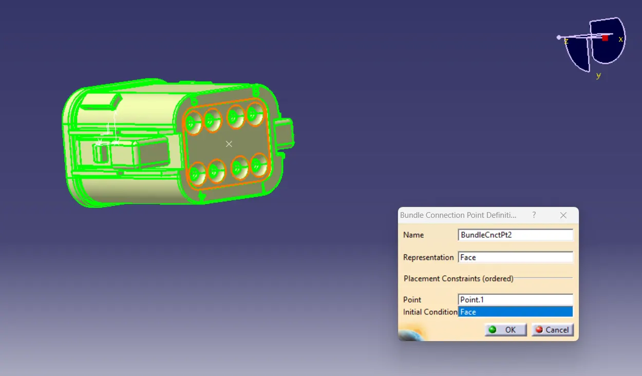
The next step is to define the connector connection point by giving the representation as the connection point, selecting the face of contact, coincidence direction as Y axis and orientation direction as X axis.
2. Connector [Tyco 174357-2]
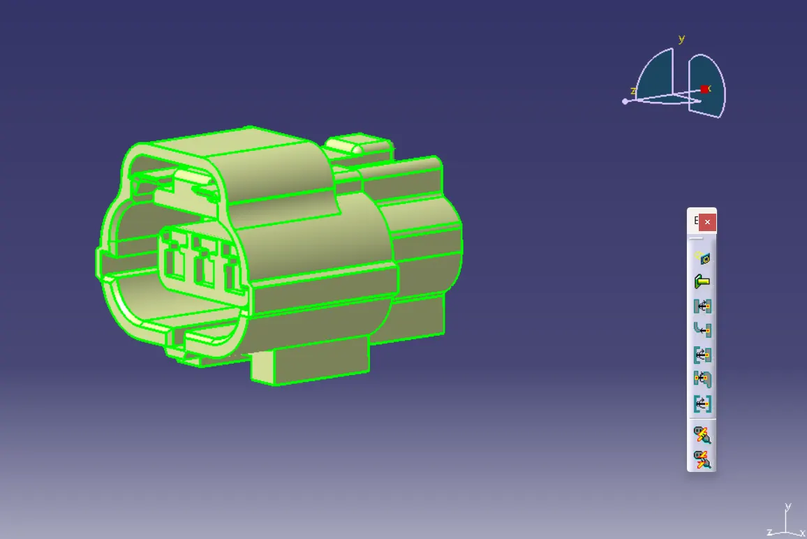
Connector connection point:
Create midpoint on the mating face of the connector and create an axis system as shown below by taking Y-axis in the direction of mating face, X-axis in the direction of lock side and Z- axis in the direction perpendicular to x and y axis respectively.
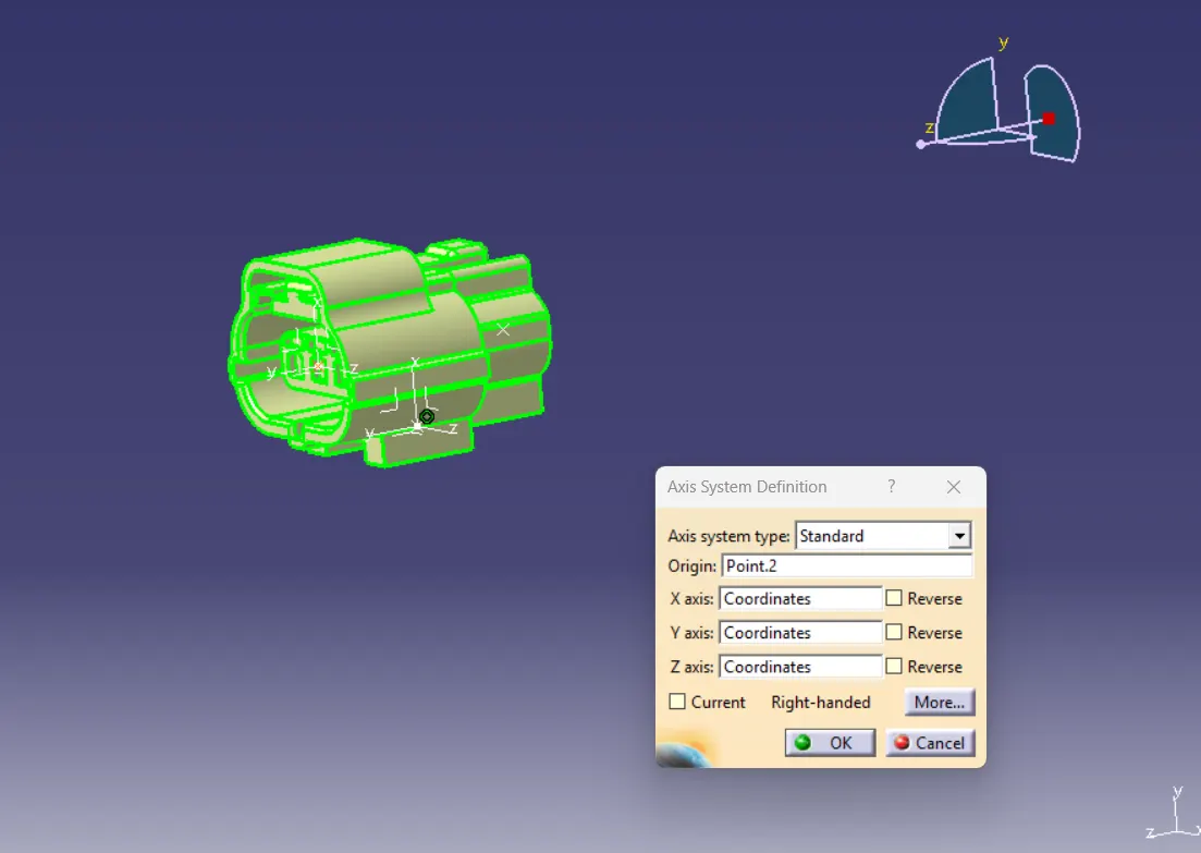
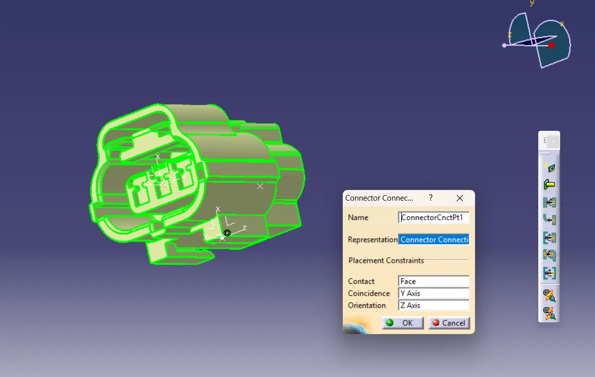
Bundle connection point:
By using the define bundle connection point command available in the electrical part design workbench and by selecting the face of bundle entry side and the created bundle centre point define the bundle connection point of connector compatible part.
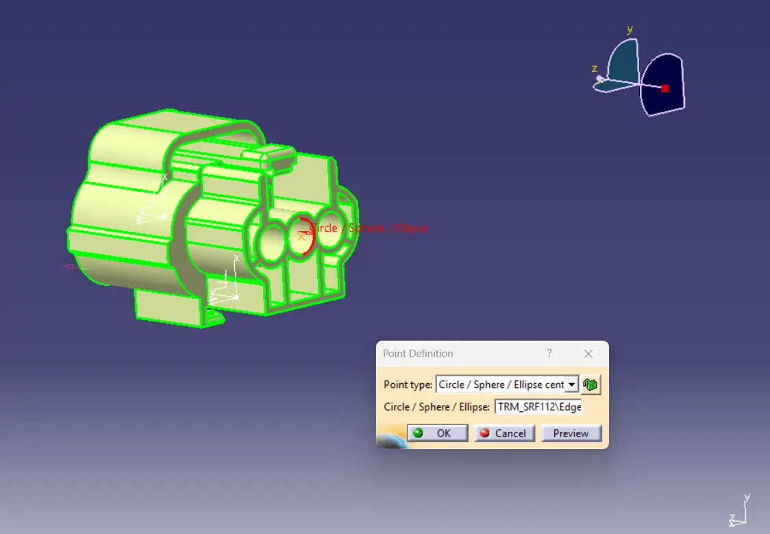
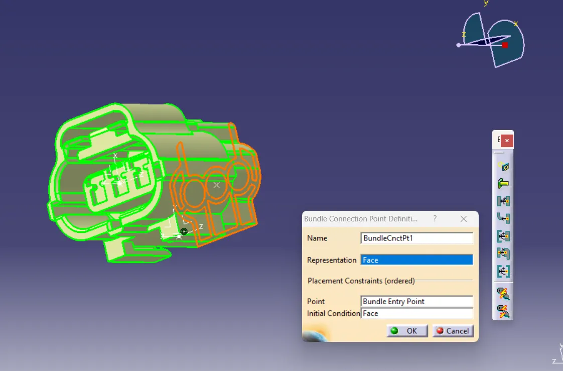
Switch to the Electrical part Design workbench to define the component as a connector and for this component is 3 as shown below.
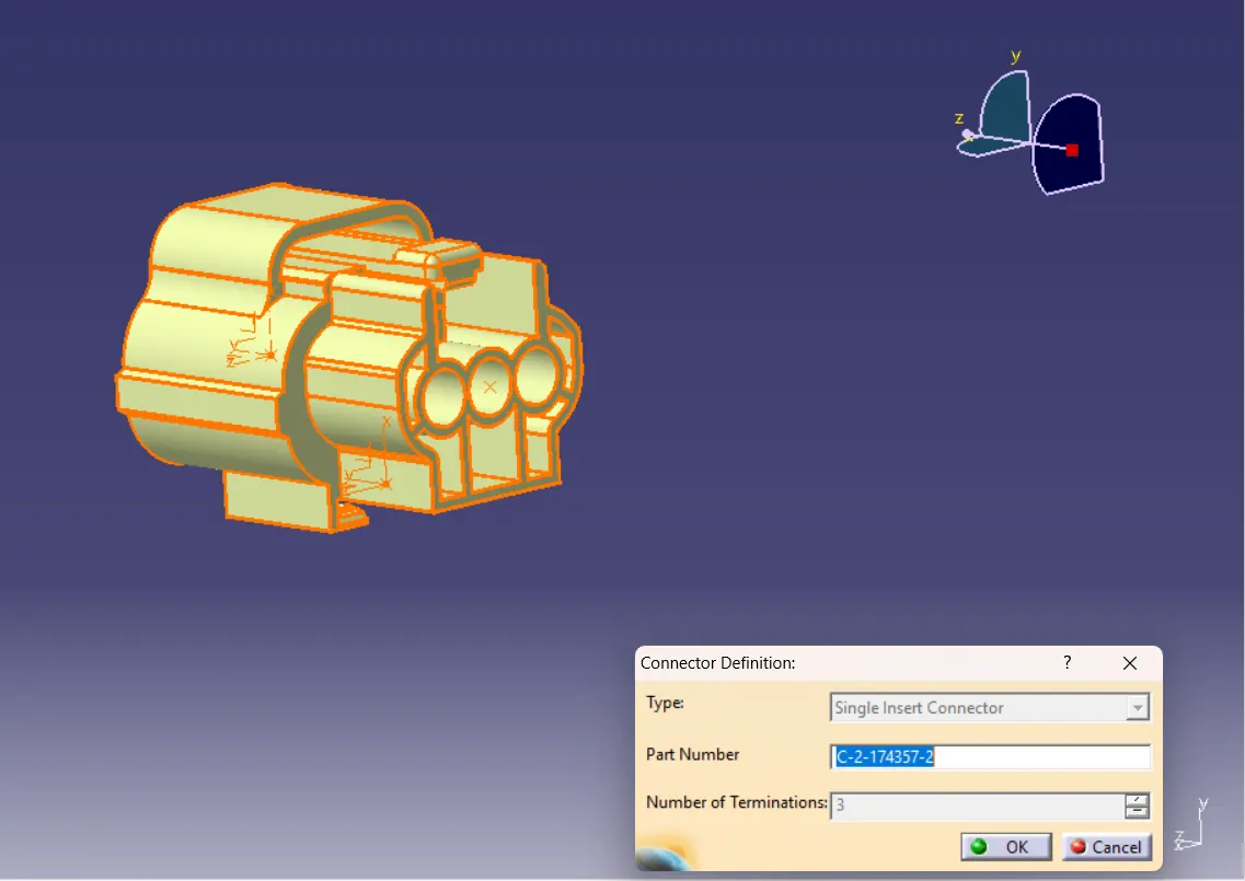
For the compatible part having cavity clip arrangement we have to define the cavity connection point by defining the representation, contact face, coincidence axis and orientation direction by selecting the representation as cavity clip point, the face of contact of the cavity clip, coincidence direction as Y axis and orientation direction as X axis.
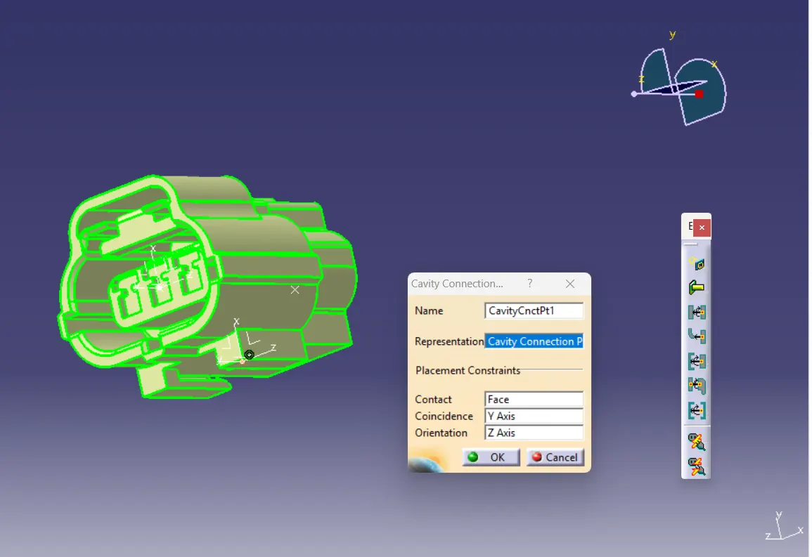
3.Connector clip [Tyco 85229-1]
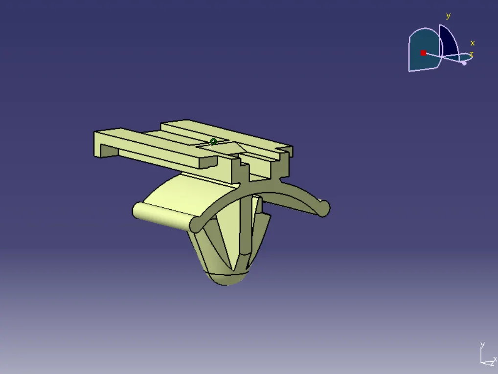
Connector clip is then opened in the cad part file and create the centre point and axis system with respect to the compatible part having cavity clip arrangement and the locking mechanism.
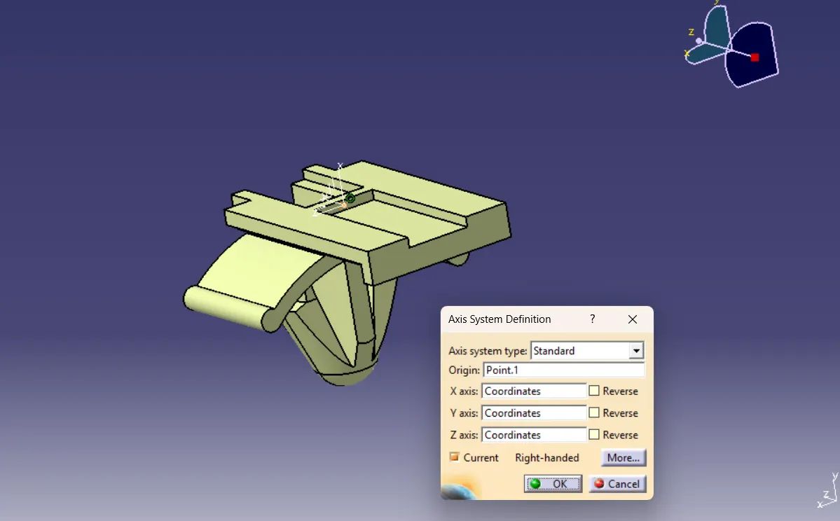
This is a connector clip here first we want to create a point on the connecting face and insert an axis system in that point and its orientation should be same as the connector to which it is connected after that switch to electrical part design and define the part as mounting equipment and the define cavity connection point as shown below.
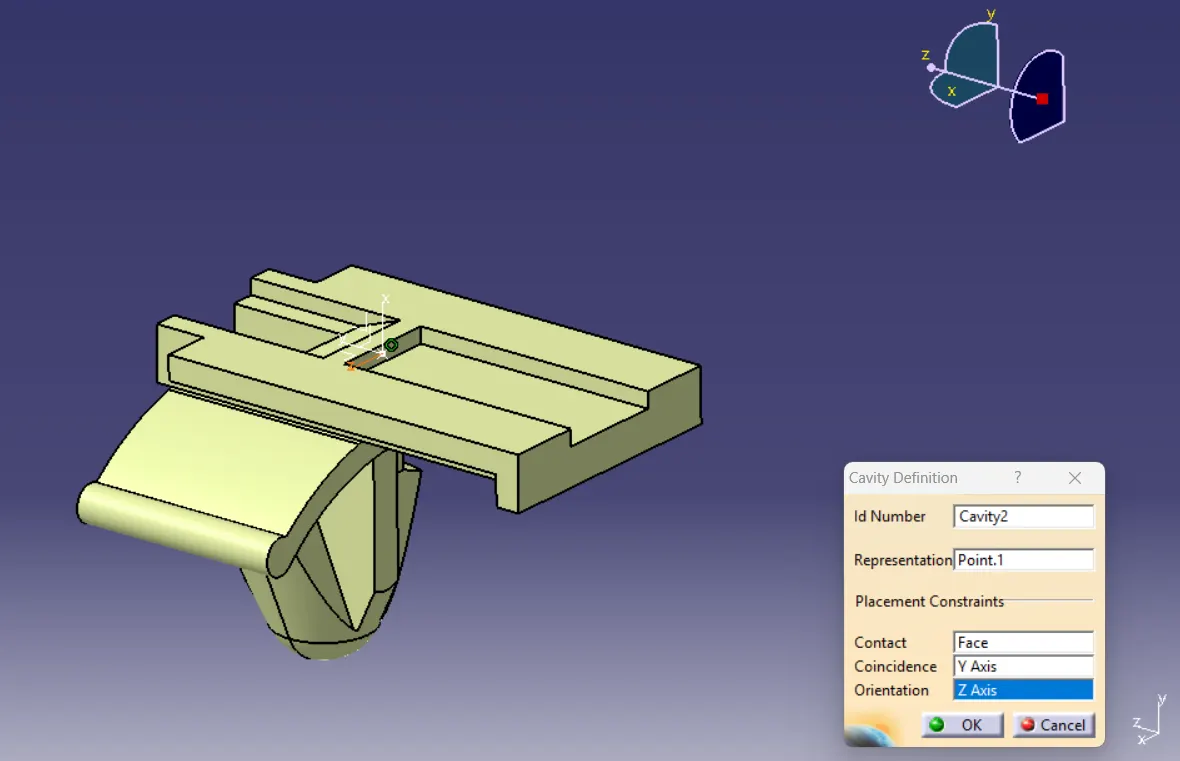
ELECTRIC ASSEMBLY DESIGN:
Open the electrical assembly design workbench by copying and pasting them or by adding the existing component command available in the insert toolbar.
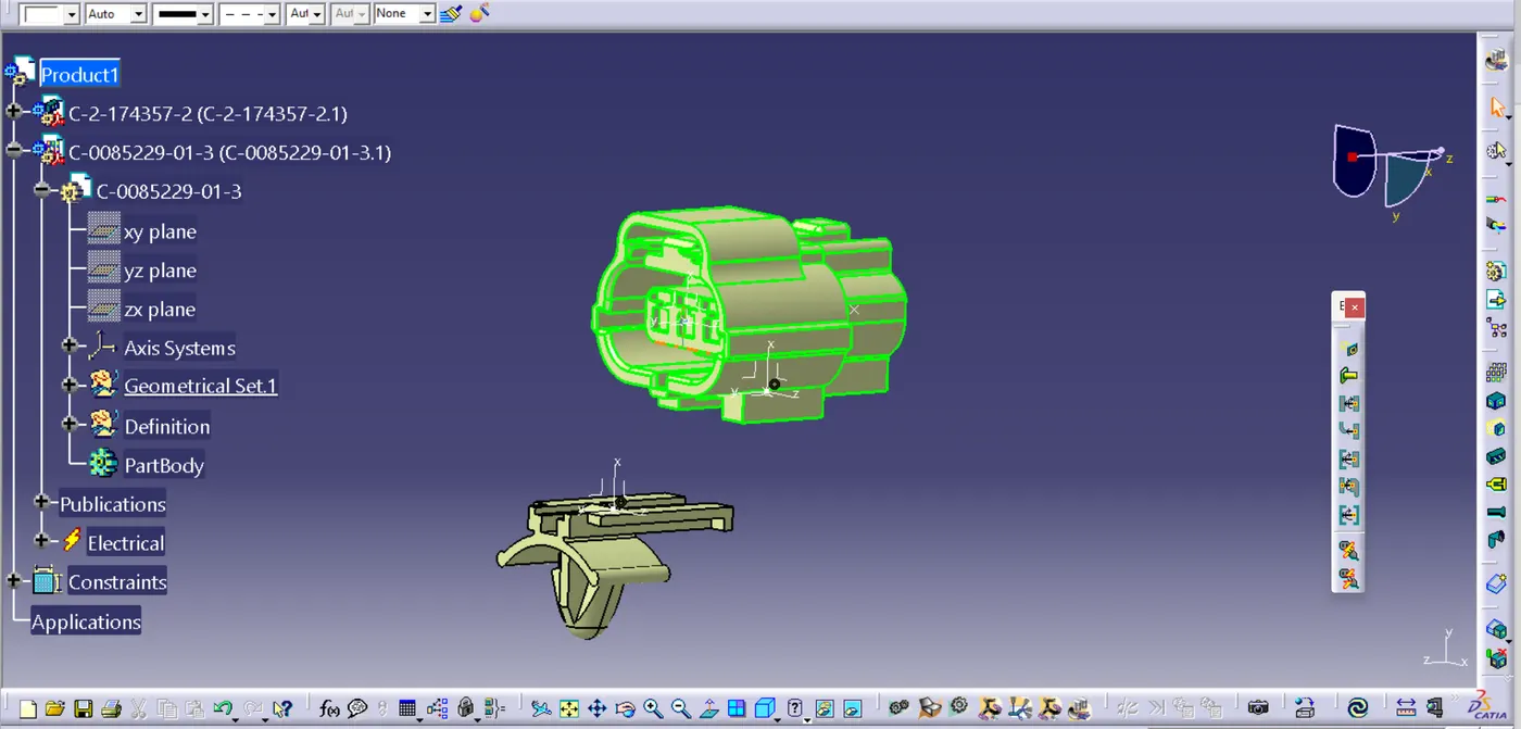
Then click the Assembly tool and select the clip and connector to assemble.
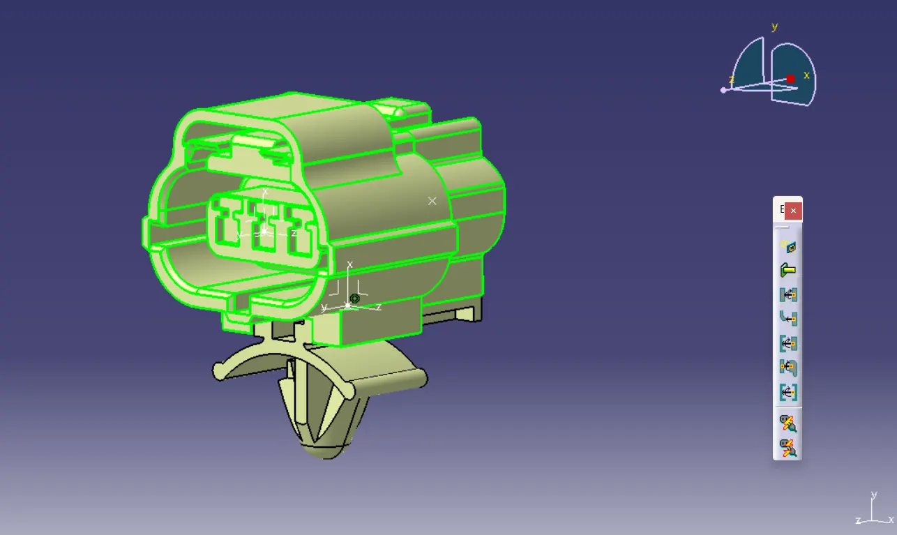
conclusion:
The connector is successfully designed in CATIA V5