Wiring harness design in CATIA V5 - 3D modeling Week 2 Challenge
Objective:
- To download the 3D CAD files from the fiven website and to define them as electrical components and to make a catalouge for the components.
Introduction
Connector
- An electrical connector is an electro-mechanical device used to create an electrical connection between parts of an electrical circuit, or between different electrical circuits, thereby joining them into a larger circuit.
Mounting clips
- They are used for supporting conduits. These clips are made of High Quality Impact Resistant Poly-amide. The mounting clips are stackable and are fixed with the help of screws on to the panel or equipment surface.
Specifications:
Connectors:
- Deutsch DT06 – 08SA
- Tyco 174357-2
Mounting Clip:
- Tyco 85229-1
PROCEDURE
For Deutsch DT06 – 08SA
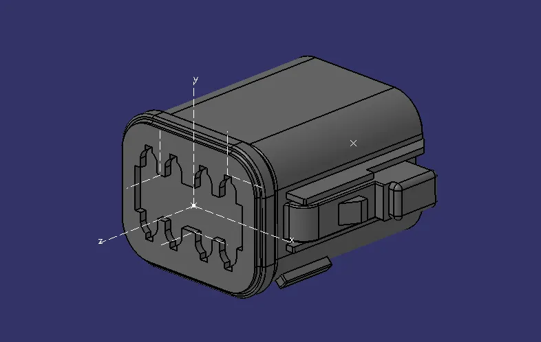
- First the open the CAD data into the catia software and define the connector based on the terminals. Create a mid point on the both sides, connector connecting side and bundle connecting side.
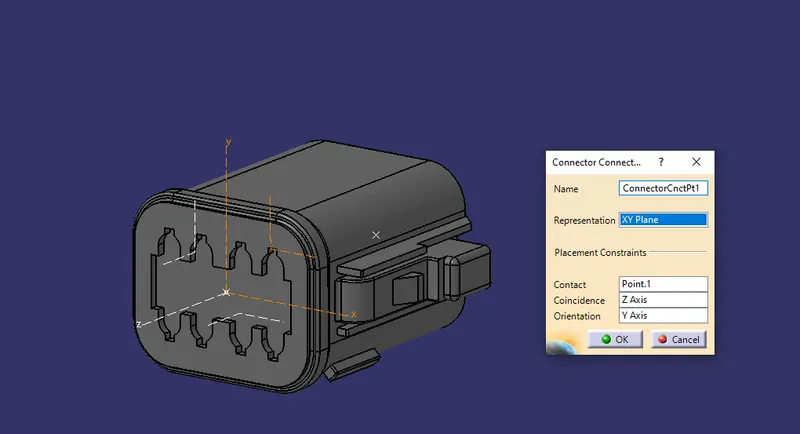
- In connector connecting side define the connector connection point with respect to the axis system.
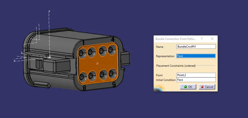
- Same way define the bundle connection point definition in the bundle connecting side with respect to the axis system created.
- After that, store that connector in the device and create a catalog seperately where all the connectors will be stored.
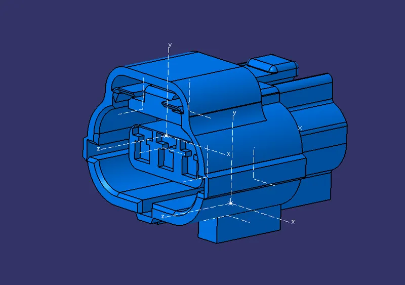
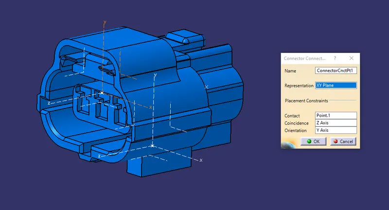
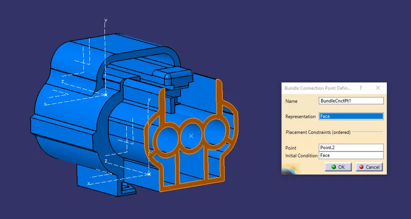
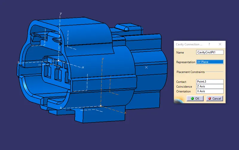
For Tyco 174357-2
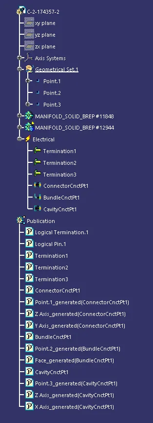
- Open the cad data into the cataia software and define the device as the connector using the electrical device definition as the connector.
- Then create a mid point on the connector connecting side and insert the axis on that point.
- After doing that, define the connectr connection point with respect to the axis created.
- Create a point on the bundle connecting side and define the bundle connection point using the electrical definition point toolbar.
- Now, define the device as the cavity using the point created on it along with the ais system.
For Tyco 85229-1
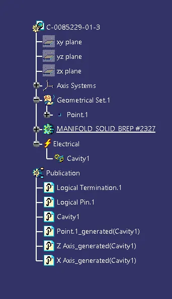
- Open the cad data into the catia software and define the clip as define equipment from the electrical device definition toolbar.
- Create a mid point and insert the axis system on that point. This axis system should be similar to the connector axis system for the cavity.
- Then define the cavity definition point using the electrical connection point definition.
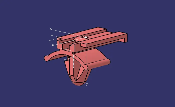
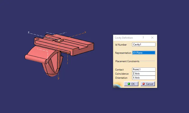
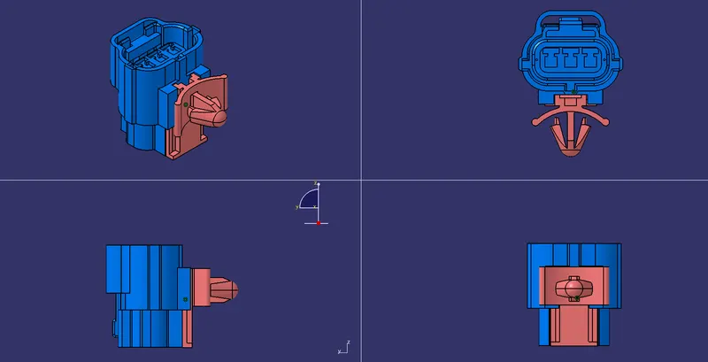
Assembly for Tyco 174357-2 and Tyco 85229-1
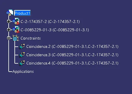
- Open the electrical assembly workbench and insert the the two electrical devices and join these two components using connect electrical devices.
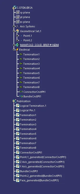
Tree Structure
For Deutsch DT06 – 08SA
For Tyco 174357-2
For Tyco 85229-1
Assembly Tree Structure