Wiring harness design in CATIA V5 - 3D modeling Week 2 Challenge
Deutsch DT06 – 08SA
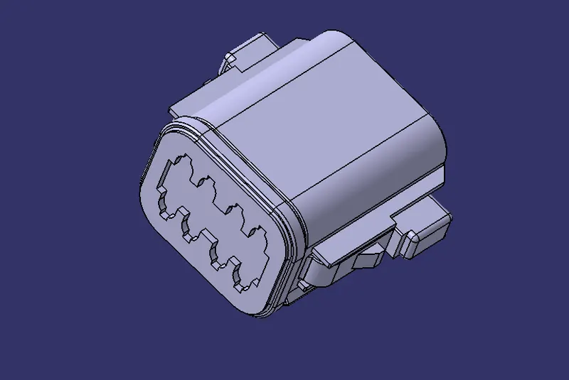
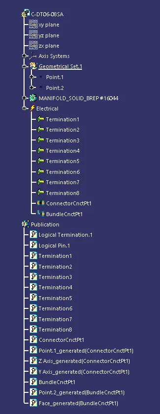
- We need to specify the part using define connector in the electrical part design workbench and need to specify number of terminals, which is for this connector is 8
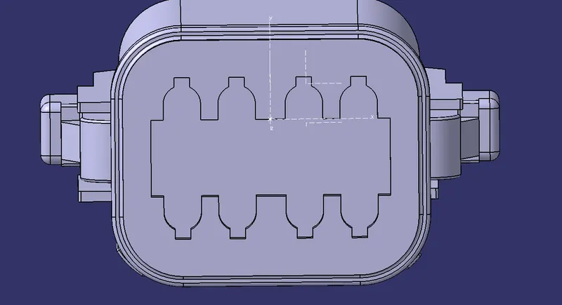
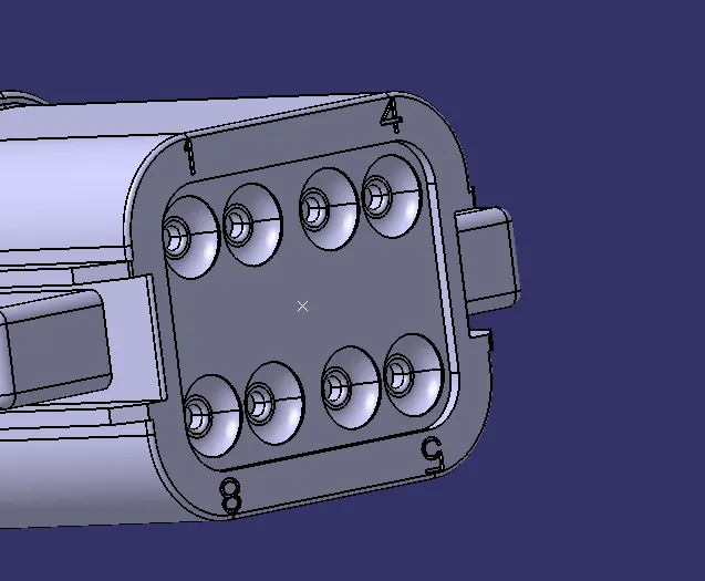
- Now we need to specify connector connecting point and bundle connecting point using Define connector connection point and bundle connection point in the electrical connection definition point workbench.
- For that we need to create a point in each connector connection side and bundle connecgtion side which is somewhere near to the middle of the connection.
- For connector connecting side we need to insert an axis system and the pattern of insertion should be followed in the connector also.
Connector connecting side
Bundle connecting side
TREE STRUCTURE
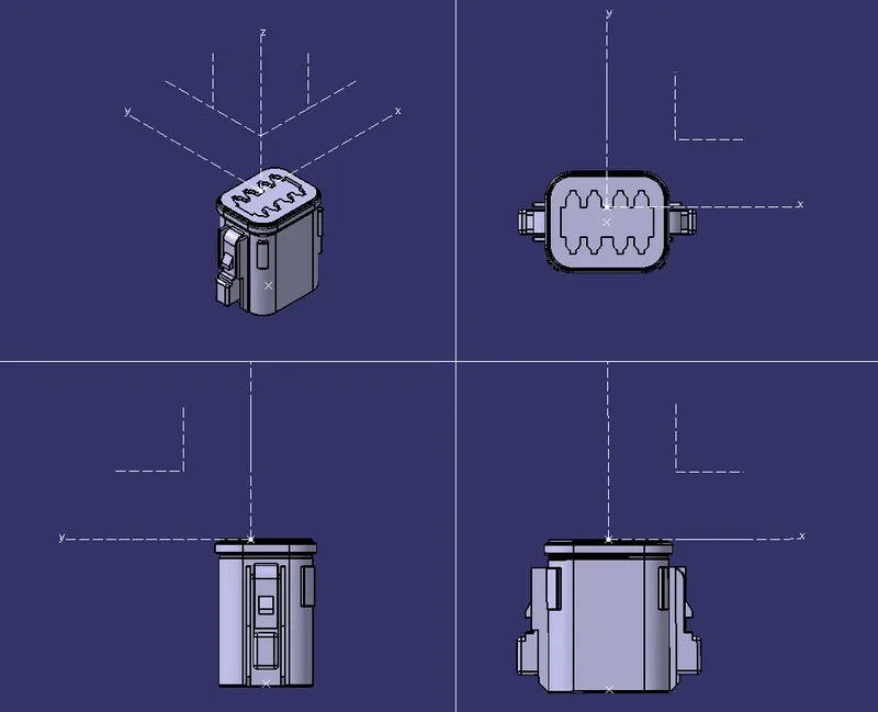
Tyco 174357-2
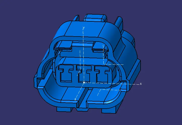
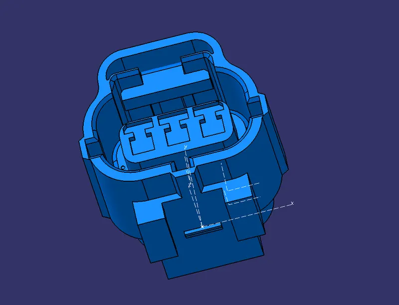
- The process is same as that above but in this we need to define an extra point and an axis system for the cavity to come and mount properly.
- As in the third picture the cavity mounting part is defined after inserting an axis system and defined it using the Define cavity connection point.
CONNECTOR CONNECTING SIDE
BUNDLE CONNECTION SIDE
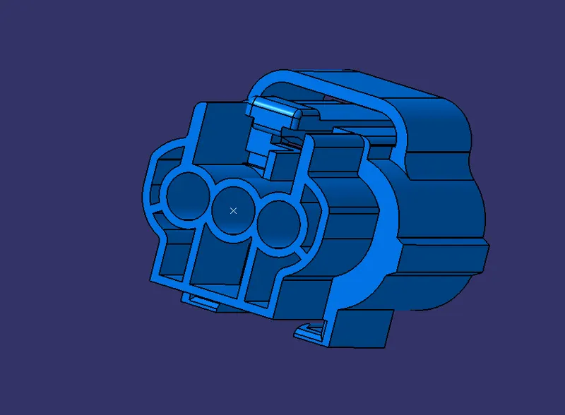
CAVITY MOUNTING SIDE
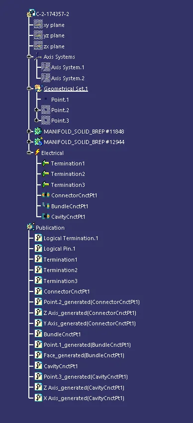
TREE STRUCTURE
Tyco 85229-1
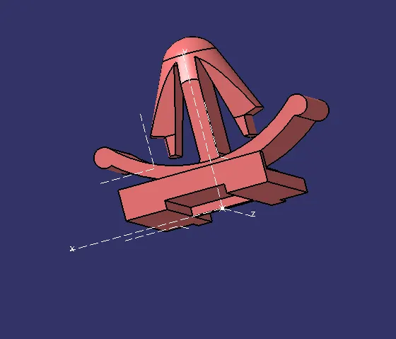
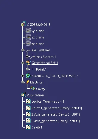
- The cavity must be defined as a mounting equipment from the electrical device definition workbench
- Then it should be defined as a cavity from the electrical connection definition point workbench.
- Cavity also should be marked in the same way as the cavity connecction point is defined.
- The point on the cavity must be slected in such a way that the point selected on the connecter must coincide.
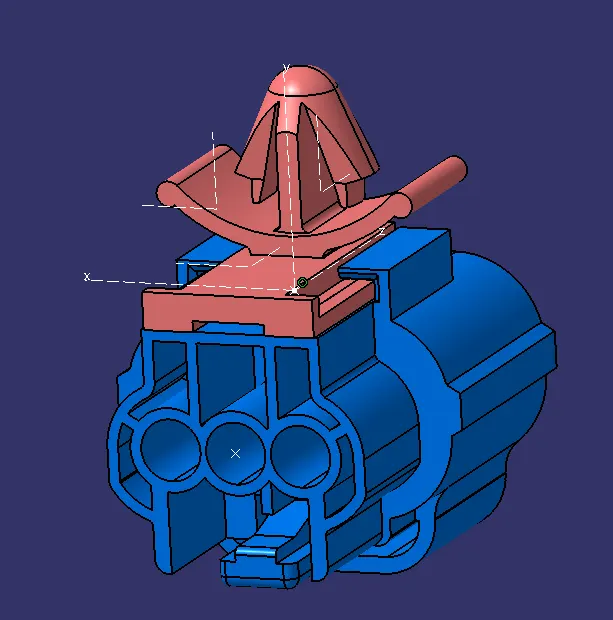
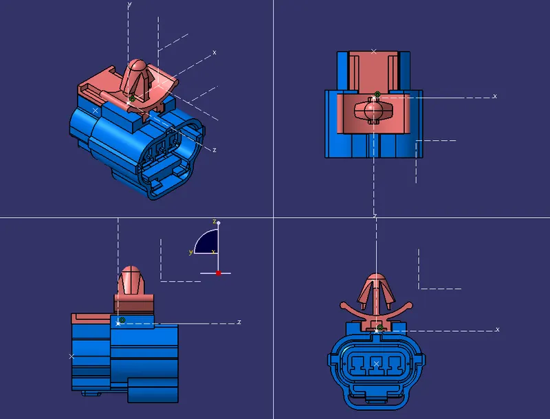
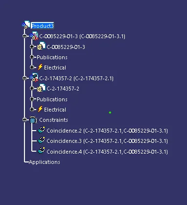
ASSEMBLY OF CONNECTOR AND CAVITY
Assembly is done using connect electrical devices tool in electrical assembly work bench