Wiring harness design in CATIA V5 - 3D modeling Week 2 Challenge
WIRING HARNESS DESIGN IN CATIA V5- CONNECTOR & THE MOUNTING CLIP
AIM: To create the connector (male and the Female part)and the mounting clip wiring harness assembly by using catia V5 software
Objective: The wiring harness assembly process of a connector basically involves the following steps
They are:
- Create / download the 3D connector files
- Create the required geometrical requirements
- Defie the part as the electrical
- .Define the bundle connection point
- Define the connector connection point
- Define the cavity connection point
- Define the cavity
Connector definition:
An electrical connector is an electro magnetic device used to create an electrical connection between parts of an electrical circuit, or between different electrical circuits, thereby joining them into a larger circuit. Most electrical connectors have a gender
1. The male component,called a plug.
2. The female part called as the socket.
The connection may be removable (as for portable equipment), require a tool for assembly and removal, or serve as a permanent electrical joint between two points.
The steps involved are:
- Download the connector cad files
- Defining them electrically by providing proper geometrical requirements
- Creating the harness assembly
- Creating teh catalogue electrical
1.Download the connector cad files:
Download the mentioned cad files of the connector from the TE.com
Deutsch DT06 – 08SA :
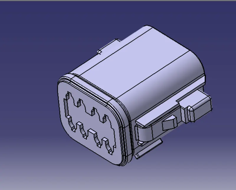
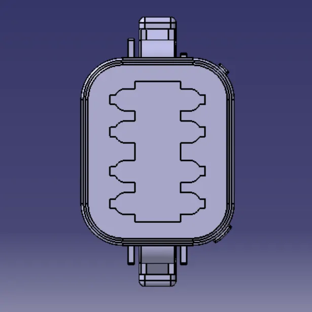
From the connector first we need to identify the bundle pooint and the mating point
The mating point is
The bundle point is
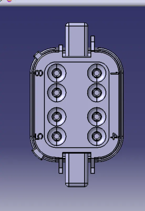
Once the parts atre identified then create the required geometrical constraints in the part work bench mechanical
1.create a point on the bundle entry point
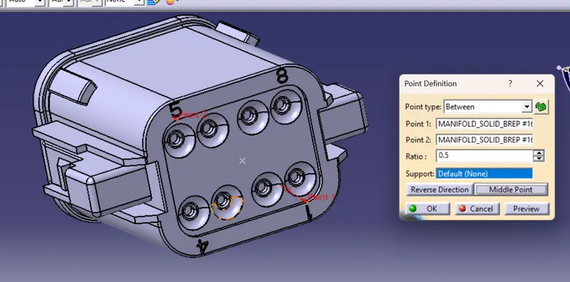
Now create a point and the axis system at the mating side
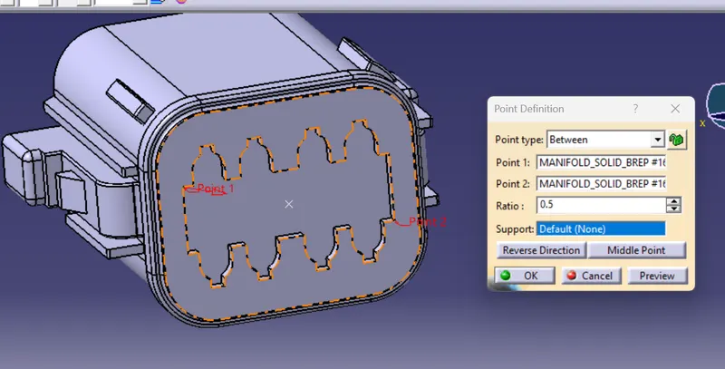
now create an axis system at the connector mating side
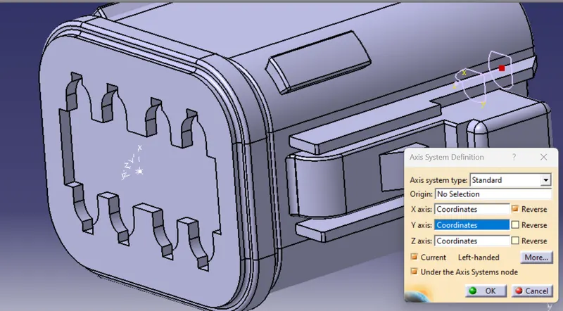
The axis system arrangement as follows
- The Y axis normal to the mating connector face
- The X asis along the directioon of orientation for the axis in the locking side
- The Z axis along the right or the left side of the mating connection
2.Define the part as the electrical
Now go to the start < equipment & systems < electrical harness duiscipline < Electrical part design
Now define the part as the electrical connector by providing the part number and the number of terminations
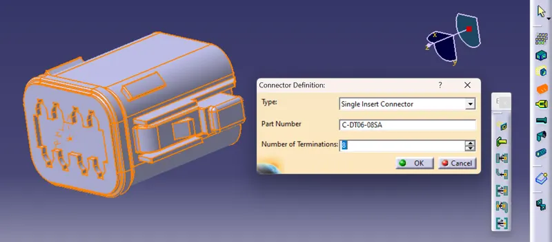
3.After that provide the bundle connection point by providing the
- Representation- Bundle face
- Point - Bundle reference point
- Initial condition - same bundle face
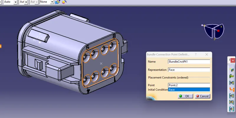
4. Define the connector connection point:
once the bundle connection point is done provide the connector connection point in the mating side by providing the
- Representaion: Connector mating reference point
- contact : Connecor mating face
- Coincidence: The Y axis which is normal to the mating face
- Orientation : The X ais along the tangent face of the connector
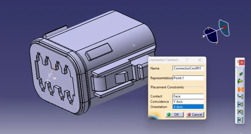
Now save the part document as the electrical cad part
5. Now create an electrical catalogue
first File< New< Catalogue document the window pops up
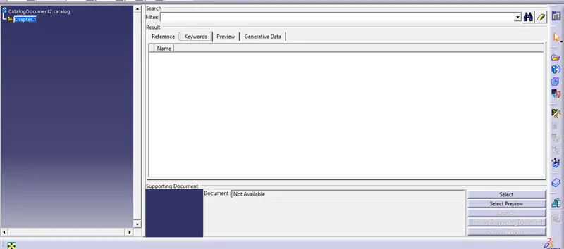
There is an option called the ADD FAMILY CREATE
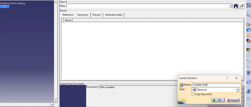
Now save the catalogue in the desired location
6. Add the electrical cad file to the electrical connector catalogue
An electriical catalogue is a document where we vcan store all the electrical componemnts such as th connectors , mounting clips, push pins where an electrical design can access and adopt the required changes
Now in the electrical cad design go to store device and add the cad part to the catalogue
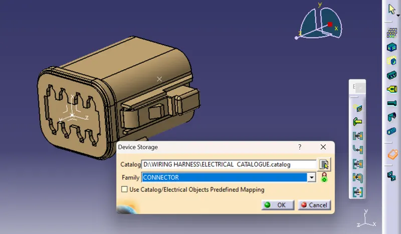
Now click OK so the catalogue is created and the part is stored
The tree structure is
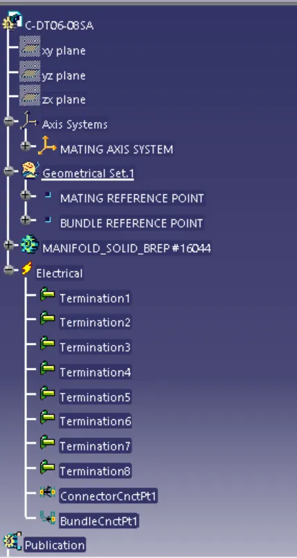
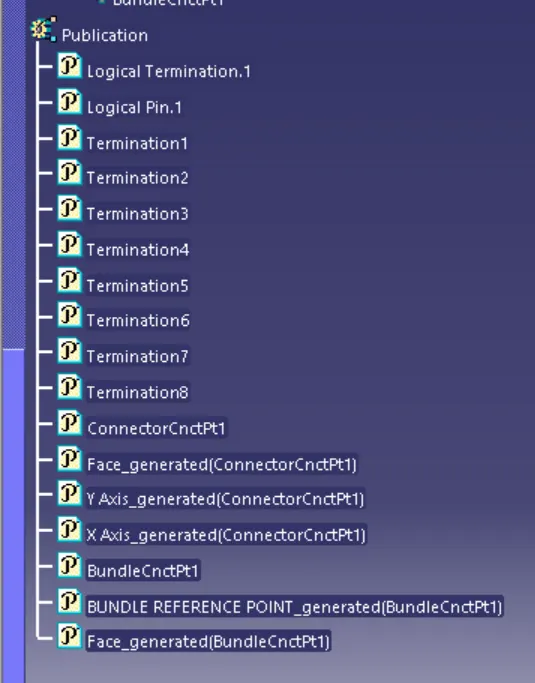
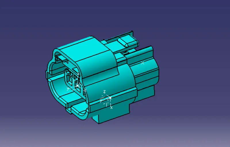
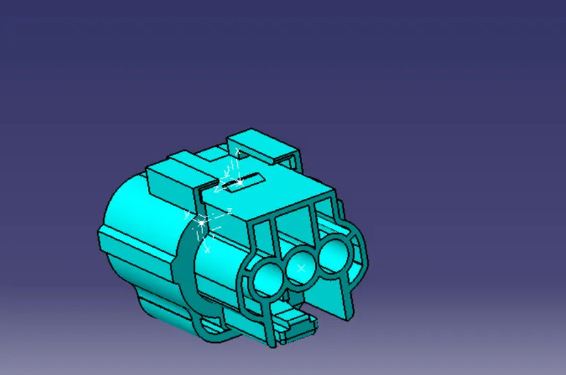
2. Download the Tyco 174357-2
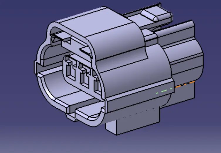
From the connector first we need to identify the bundle pooint and the mating point
The mating point is
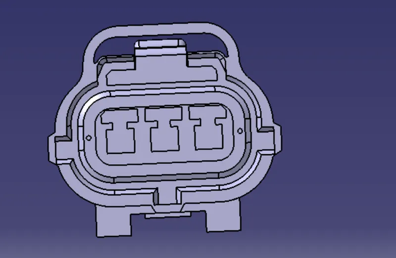
The bundle wire entry point is
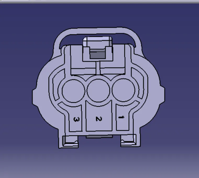
Once the parts atre identified then create the required geometrical constraints in the part work bench mechanical
1.create a point on the bundle entry point
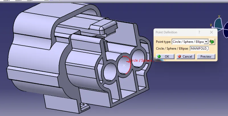
Now create a point and the axis system at the mating side
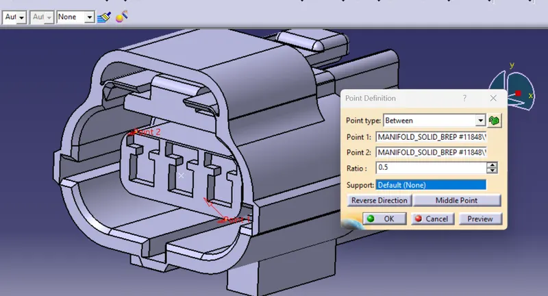
now create an axis system at the connector mating side
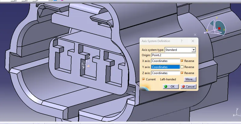
Create the cavity connection point and the axis system
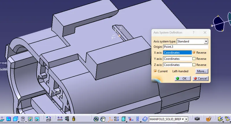
2.Define the part as the electrical
Now go to the start < equipment & systems < electrical harness discipline < Electrical part design
Now define the part as the electrical connector by providing the part number and the number of terminations
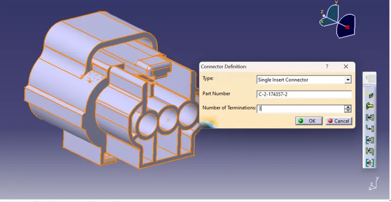
3.After that provide the bundle connection point by providing the
- Representation- Bundle face
- Point - Bundle reference point
- Initial condition - same bundle face
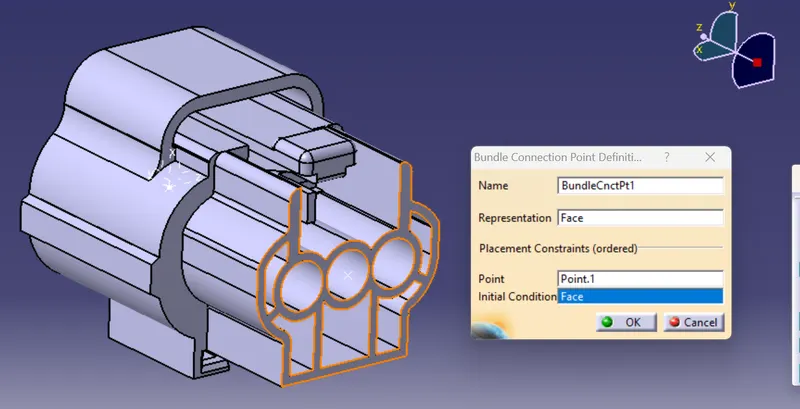
4. Define the connector connection point:
once the bundle connection point is done provide the connector connection point in the mating side by providing the
- Representaion: Connector mating reference point
- contact : Connecor mating face
- Coincidence: The Y axis which is normal to the mating face
- Orientation : The X ais along the tangent face of the connector
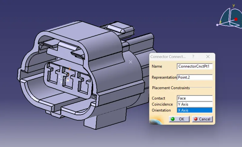
5.Define the cavity connection point
- Representaion: Connector mating reference point
- contact : Connecor mating face
- Coincidence: The Y axis which is normal to the mating face
- Orientation : The X ais along the tangent face of the connector
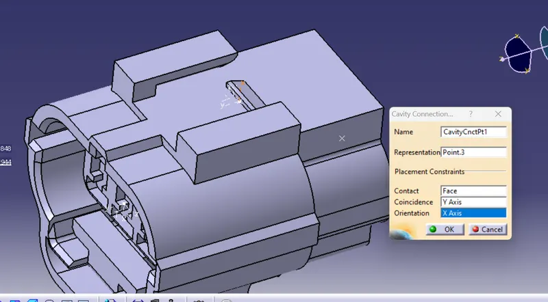
Now save the electrical CAD file and store it in the catalogue created
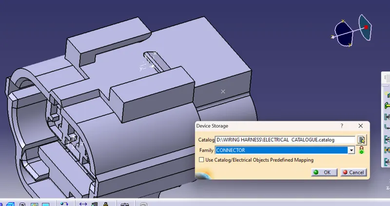
The tree structure is
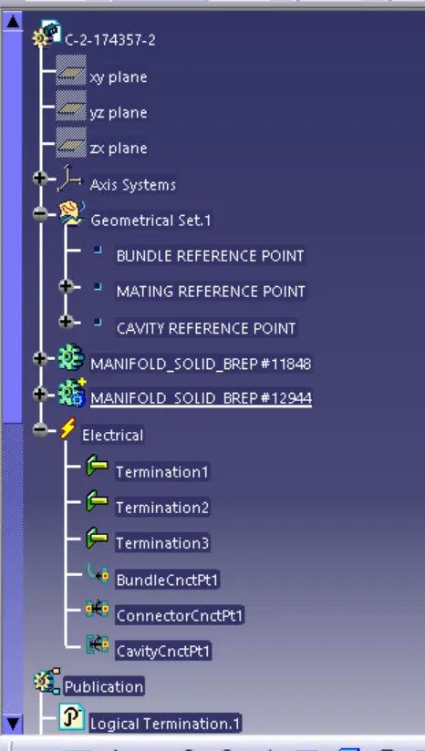
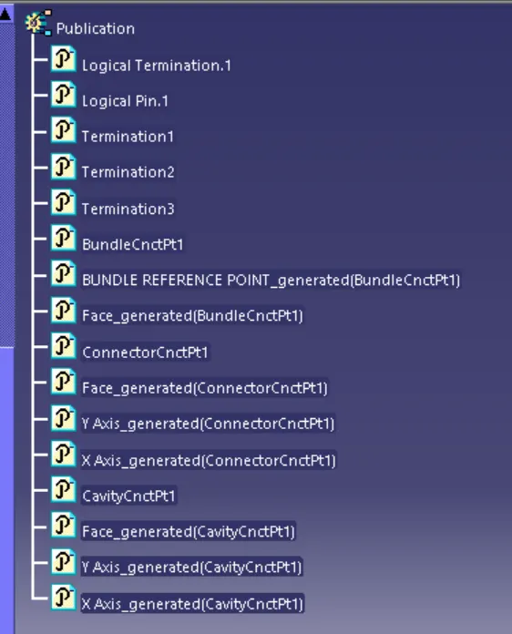
3.Download the Tyco 85229-1 from the website
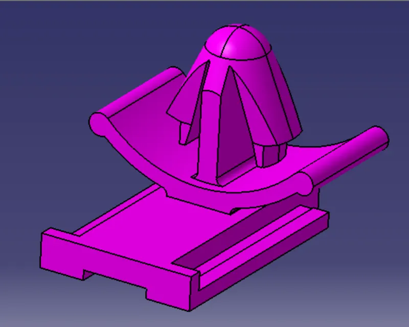
The above CAD file is a mounting equipment
create an axis and the cavity reference point
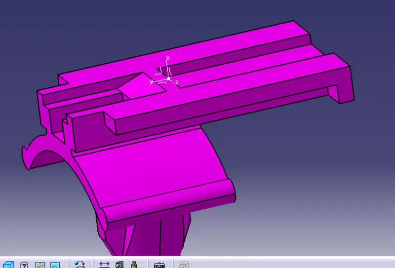
Define the cavity for the part file
- Representaion: Connector mating reference point
- contact : Connecor mating face
- Coincidence: The Y axis which is normal to the mating face
- Orientation : The X ais along the tangent face of the connector

Now save and store the file to the catalogue created
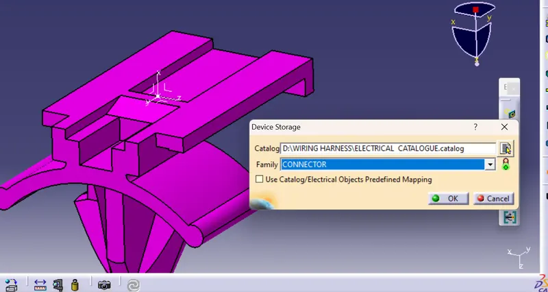
the tree structure is
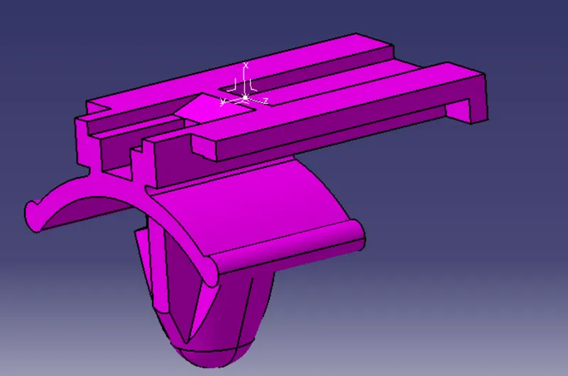
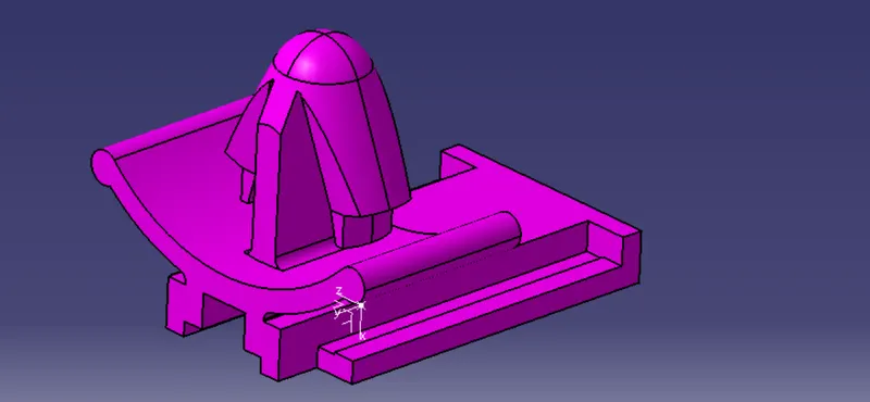
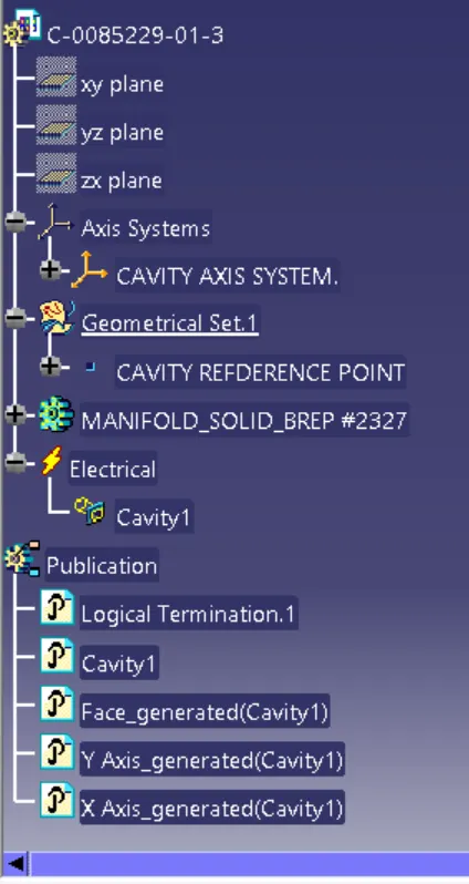
Now create the wiring harness electrical assembly for the connector and the mounting equipment
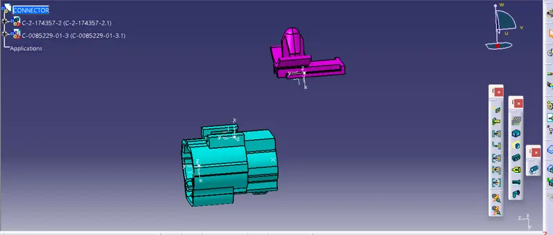
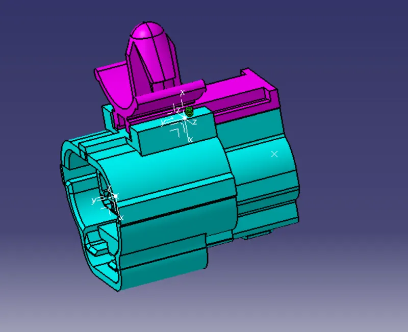
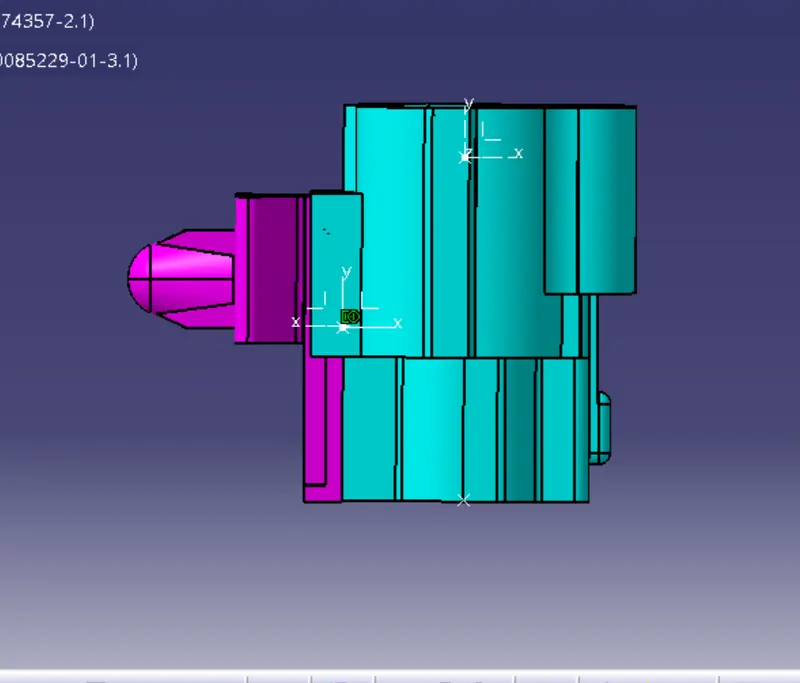
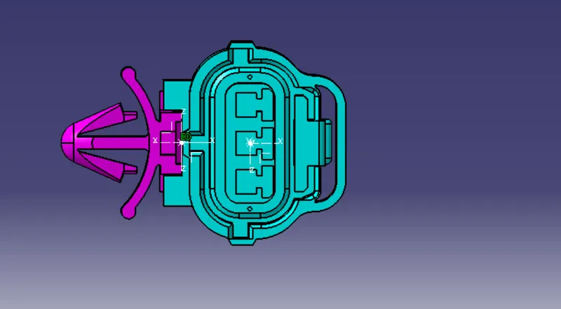
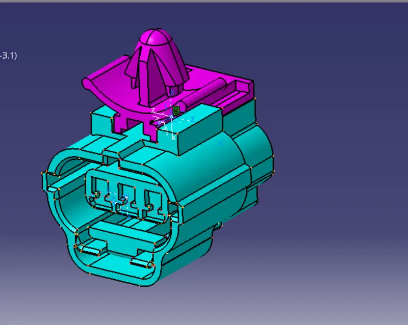
The tree structure is
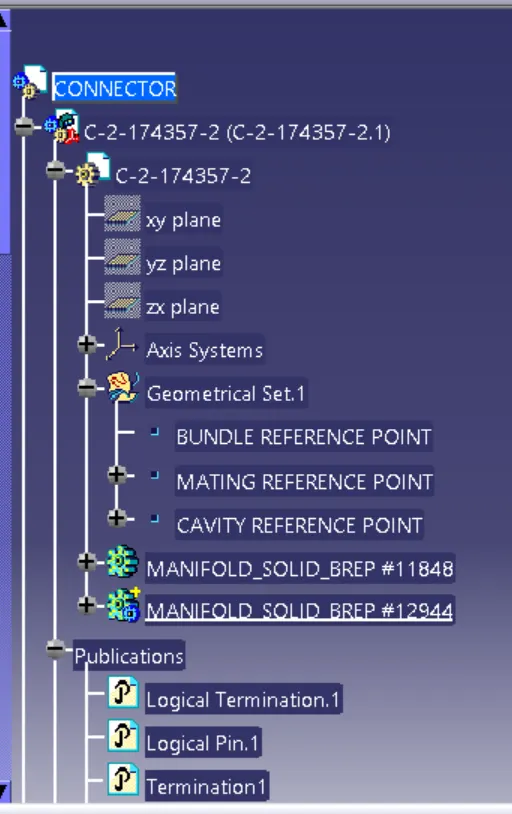
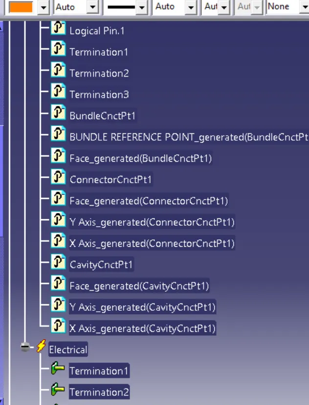
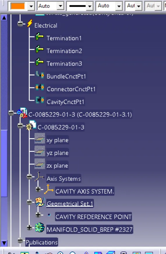
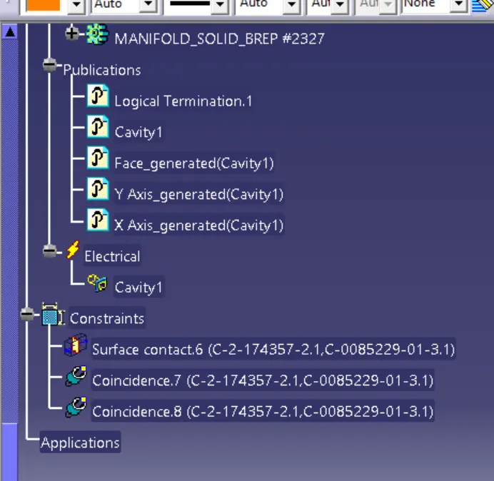
Conclusion : Thus the CAD connector related files are downloaded from the website and define them as the electrical part abd make the proper assembly and submitted all the part files along with the aseembly and the Electrical catalogue document in the browse option dialogue box