Wiring harness design in CATIA V5 - 3D modeling Week 2 Challenge
WEEK-2_CHALLENGE_ WIRING HARNESS DESING USING CATIA V5
OBJECTIVE:
To create the following connectors & Connector clip cad data from given link & define it as Electrical Connector using Electrical Part design Workbench. Define all the necessary properties to Connectors & Clip
GIVEN DATA:
- Deutsch DT06 – 08SA ( https://www.te.com/usa-en/product-DT06-08SA.html)
- Tyco 174357-2 (https://www.te.com/usa-en/product-2-174357-2.html?source=header-match)
- Tyco 85229-1 – (https://www.te.com/usa-en/product-85229-1.html?q=85229&source=header)
TOOL USED: CATIA V5
ELECTRICAL PART DESIGN WORKBENCH:
CONNECTORS
An electrical connector, is an electro-mechanical device used to join electrical termination and create an electric circuits. And these connectors consist of Housings, Terminals, Wedge, Locks, Seals, Cavity, Mounting cam and etc., And the following connectors and its electrical definings are,
1_ DEUTSCH - C-DT 06 - 08 SA
STEP_1: Create/Download the CAD data from the given link.
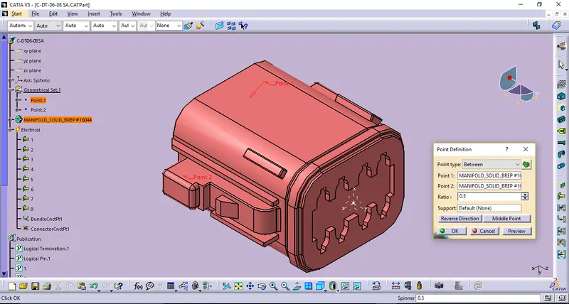
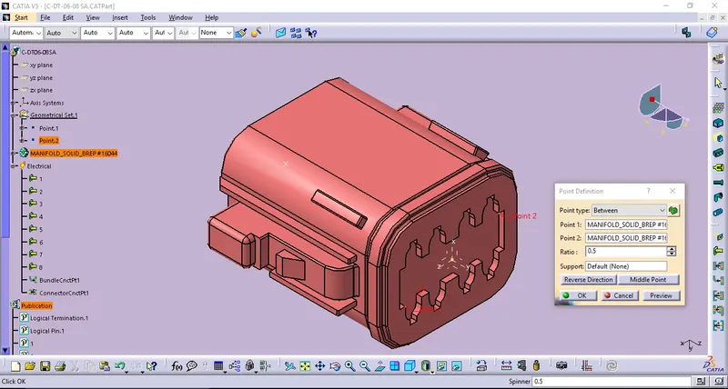
STEP_2: Creating points.
Point created for Bundle entry face by defining Point Definition.
Point created for Connector connection face by defining Point Definition.
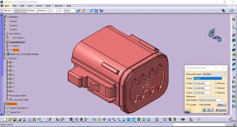
STEP_3: Creating Axis system.
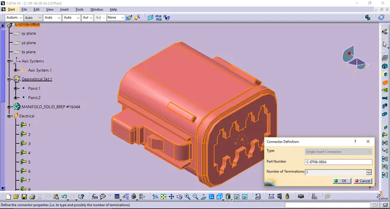
STEP_4: Defining connector
By using Connector definition thus the following connector becomes defined as Single insert connector with 8 terminals on itself.
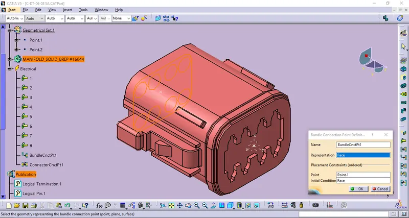
STEP_5: Defining Bundle Connection point definition.
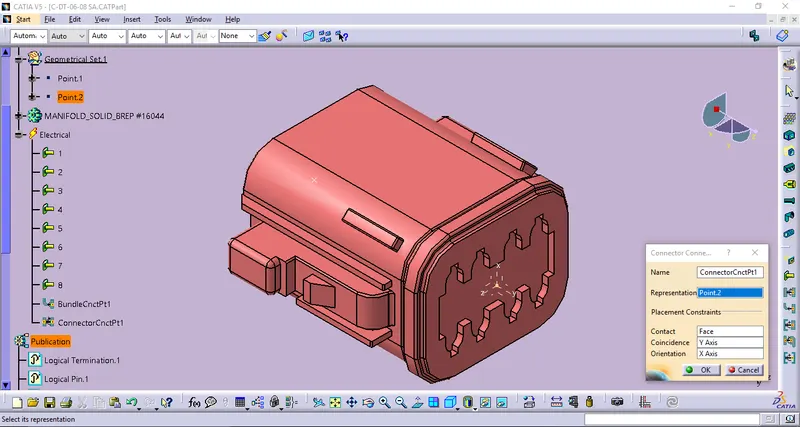
STEP_6: Defining Connector Connection
STEP_7: Then store data by using Store device definition to the apropriate catalog like Connector catalog.
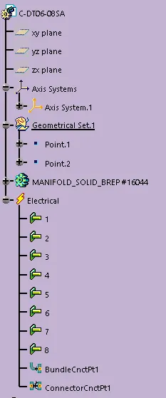
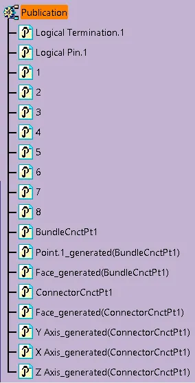
TREE STRUCTURE:
2_ TYCO - C-174357 - 2
STEP_1: Create/Download the CAD data from the given link.
STEP_2: Creating points.
Point defined for bundle entry ref,
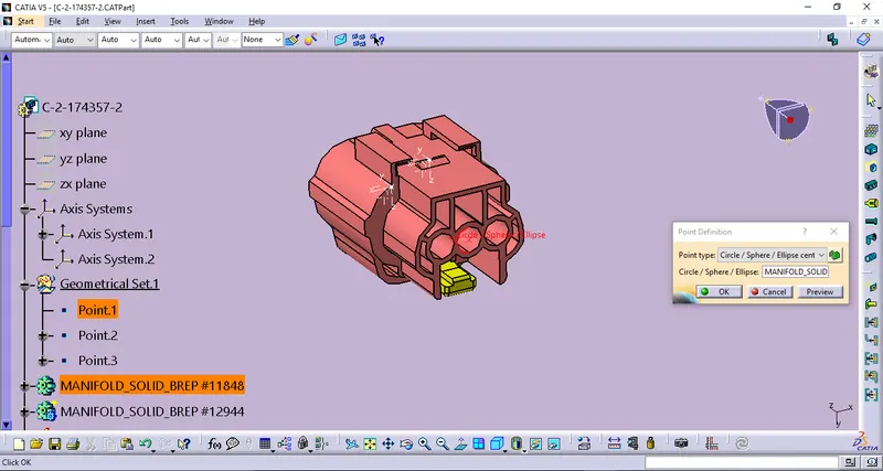
Point defined fro Connector connection ref,
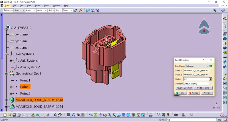
Point defined for Cavity connection ref,
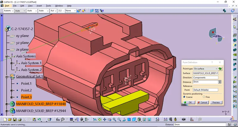
STEP_3: Creating Axis system.
Thus the following Axis system.1 which represents for connector connection.
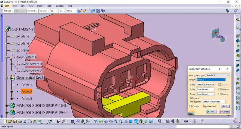
Thus the following Axis system.2 which represents for cavity connection.
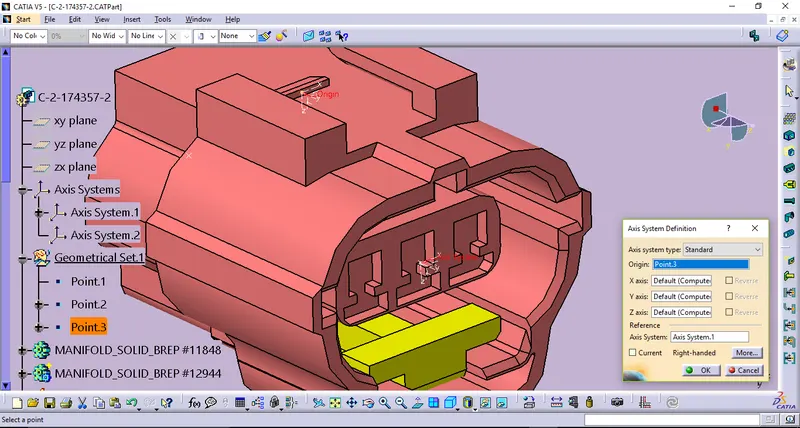
STEP_4: Define connector definition.
By using Connector definition thus the following connector becomes defined as Single insert connector with 8 terminals on itself.
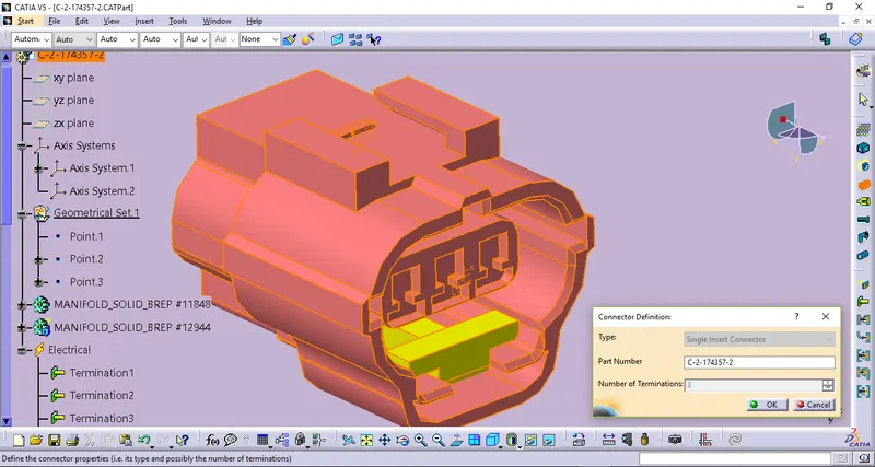
STEP_5: Defining Bundle Connection point definition.
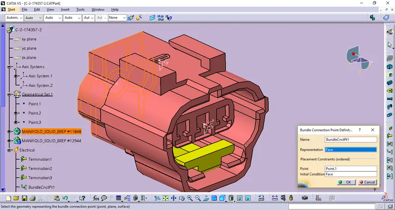
STEP_6: Defining Connector Connection definition.
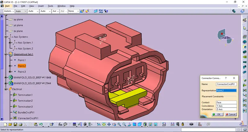
STEP_7: Defining Cavity Connection definition.
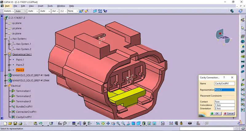
STEP_8: Then store data by using Store device definition to the apropriate catalog like Connector catalog.
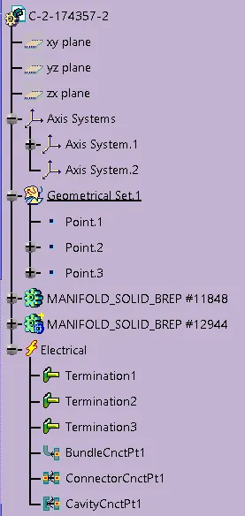
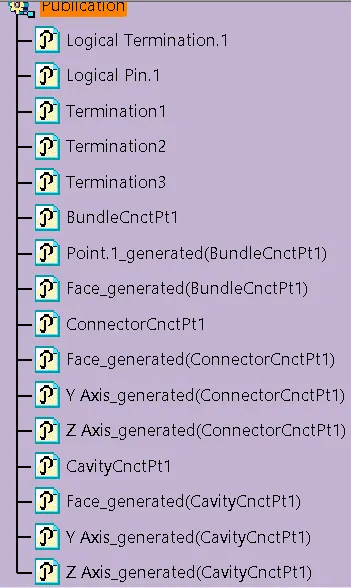
TREE STRUCTURE:
CLIPS & CLAMPS
Clips & Clamps are used to fix wiring harness bundles by providing positive fixings. And the following clip/clamp and its definitions are,
1_ TYCO - 85229 -1
STEP_1: Create/Download the CAD data from the given link.
STEP_2: Creating points.
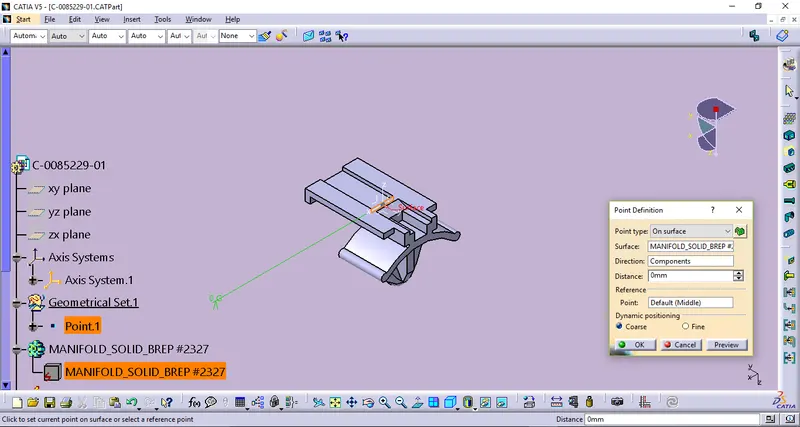
STEP_3: Creating Axis system.
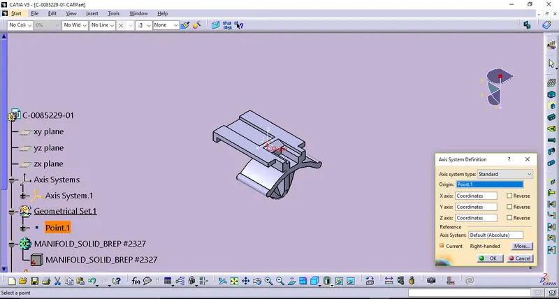
STEP_4: Ddefining it has become a mounting equipment by using Define Mounting Equipment then applying the electrical property of itself has becomes definied as by using Cavity definition.
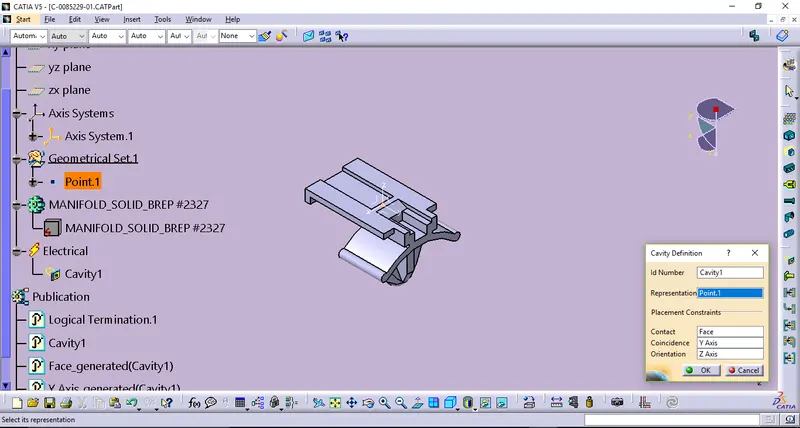
STEP_5: Then store data by using Store device definition to the apropriate catalog like Clips_Clamps catalog.
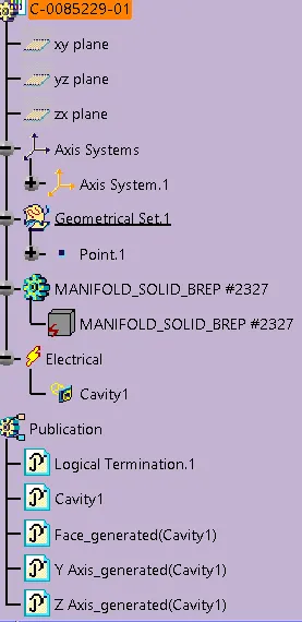
TREE STRUCTURE:
CONCLUSION:
Thus all the given Electrical components defined by using CATIA v5 Electrical Part Design Workbench.