Wiring harness design in CATIA V5 - 3D modeling Week 2 Challenge
Aim :
To Follow the given connectors & Connector clip cad data from given link & define it as Electrical Connector using Electrical Part design Workbench.
Objectives :
- Deutsch DT06 – 08SA
- Tyco 174357-2
- Tyco 85229-1
Procedure :
Deutsch DT06 – 08SA
It Was Simply Called as Automotive Housing & Connectors
These housings are designed for cable to cable connections. Their seals provide a robust seal with a high degree of environmental protection. Safe, versatile and reliable, DT plug connector housings are made from a thermoplastic which is ideal for automotive applications.You will not struggle for choice as the DT plugs are available in 2 to 12 pin options. They use size 16 DEUTSCH contacts, each with 13-amp continuous capacity. The housings feature an integrated latch for mating.
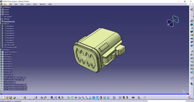
In the Above figure We Have Taken from TE resorce & Merged into Catia V5.
1.Then Selecting the Part design workbench & Taking A middle Point From The Connector Connecting Side As Well As Bundle Connecting Side based on no of terminals.
2.Taking the axis Origin of Connector connecting Point.
3.Adusting the y-axis is normal to the face of connector connectiong Point & X-axis would be locking side & Z-axis would be Up or down side.
4.Then go to the electrical part design & defining the bundle connection point As well as connector connection point wuth respect to their faces & Respresentations.
Tyco 174357-2
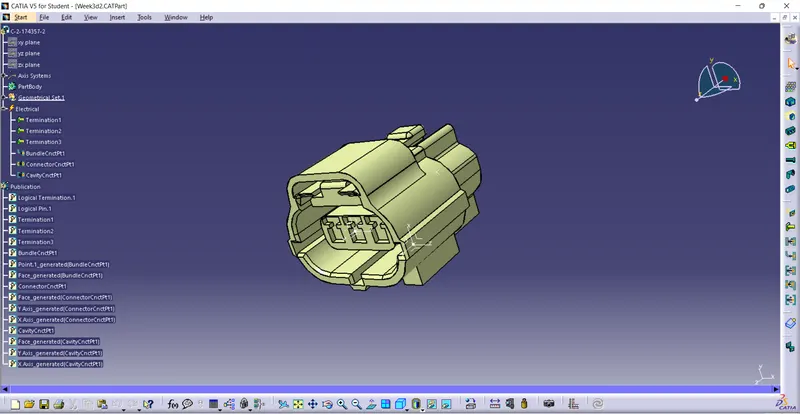
In the Above figure We Have Taken from TE resorce & Merged into Catia V5.
1.Then Selecting the Part design workbench & Taking A middle Point From The Connector Connecting Side As Well As Bundle,Cavity Connecting Side based on no of terminals.
2.Taking the axis Origin of Connector connecting Point.
3.Adusting the y-axis is normal to the face of connector connectiong Point & X-axis would be locking side & Z-axis would be Up or down side.
4.Then go to the electrical part design & defining the bundle connection point As well as connector connection point wuth respect to their faces & Respresentations.
3.Tyco 85229-1
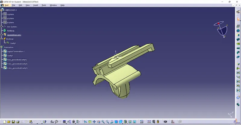
In the Above figure We Have Taken from TE resorce & Merged into Catia V5.
1.Then Selecting the Part design workbench & Taking A middle Point From face is goint to assembled thae cavity connecting point.
2.Taking the axis Origin of Connector connecting Point.
3.Adusting the y-axis is normal to the face of connector connectiong Point & X-axis would be locking side & Z-axis would be Up or down side.
4.Then go to the electrical part design & defining the bundle connection point As well as connector connection point wuth respect to their faces & Respresentations.
Defining it As a Electrical Cinnector By Assembling it on Mechamnical As well As Electical
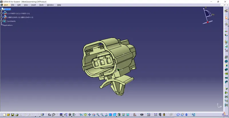
1.By Defining it As a Electrical Connector We have Assembled the Two Parts
- Tyco 174357-2
- Tyco 85229-1
& Then Split & Change their Orientation According to the Axis Of Alignment in Mechanical Assembly workbench.
2.Then Go the Electrical Assembly Design workbench & Connect them As a Electrical Device.
Conclusion :
Successfully defined given Connectors & clips as Electrical Connectors using Electrical Part design Workbench. The Results of catia files are attached given below.