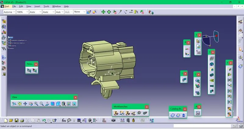
Wiring harness design in CATIA V5 - 3D modeling Week 2 Challenge
The igs format cad file of the connectors are downloaded.
After loading the cad file into the catia software,the geometrical properties of the connector are defined in the part design .After the geometrical parameter definitions ,we switch to electrical part design.There connector definition is done ,the connector connection and bundle connection point are made.The connector is finally added to a catalogue.
After the connectors are defined ,they are added to a catalogue.So a catalogue can be created at the starting
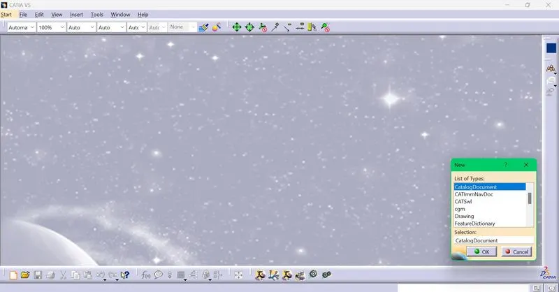
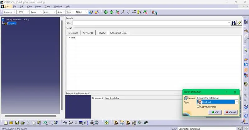
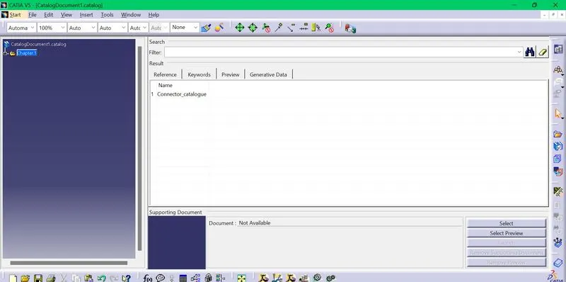
Family Connector_catalogue is created.The connectors are added using the store device option.
-Deutsch DT06 – 08SA
Point creation
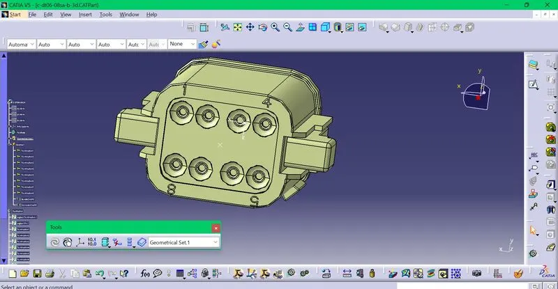
Axis creation
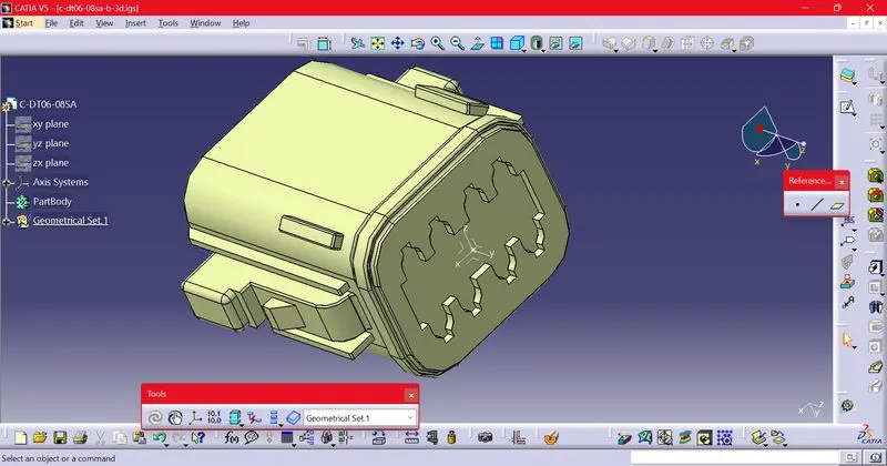
Both point and axis are created on the bundle and connector entry sides.
Next,switch to Electrical part design
Part is defined as a connector
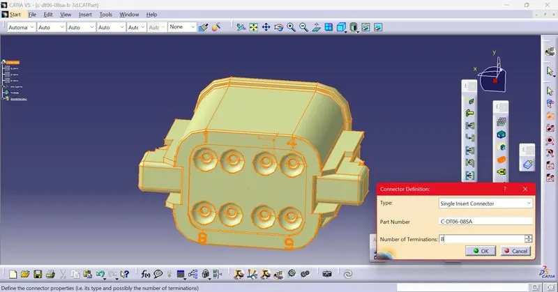
Connector connection point is defined
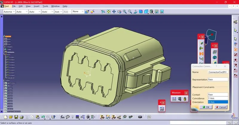
Bundle connection point is defined
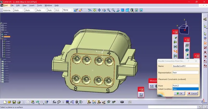
-Tyco 174357-2
Point creation
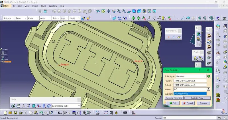
Axis creation
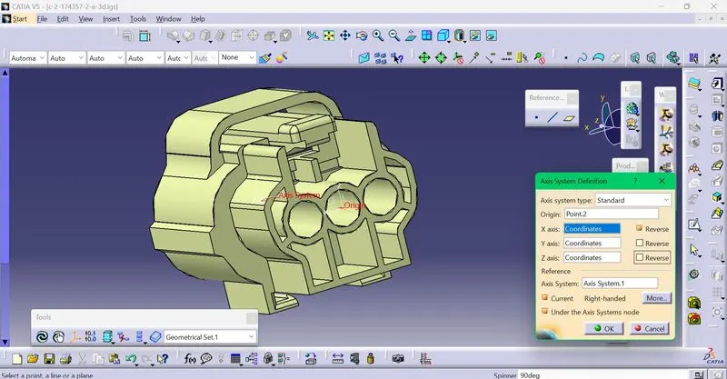
Both point and axis are created on the bundle and connector entry sides.
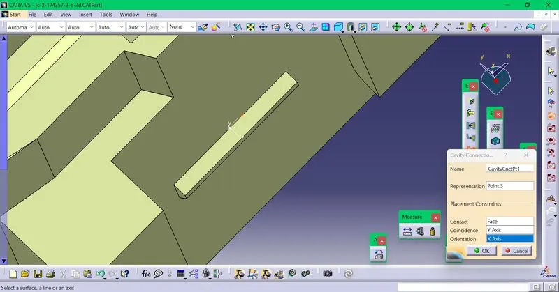
Point for cavity is also created,and axis is also made ther.
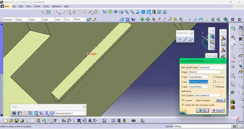
Next,switch to Electrical part design
Part is defined as a connector
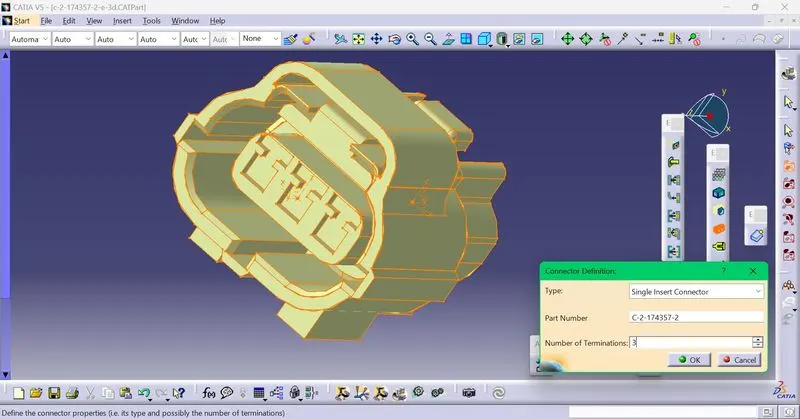
Connector connection point is defined
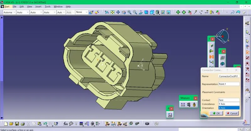
Bundle connection point creation
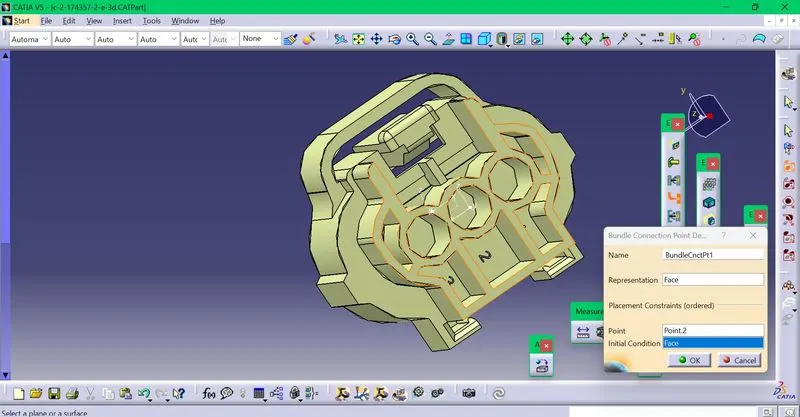
Cavity connection point is created
-Tyco 85229-1
Point creation for cavity
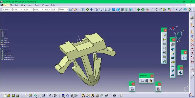
Cavity connection point creation
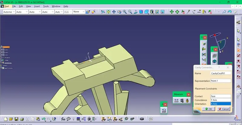
After this ,the connector and support part can be connected using the connect electrical devices option in Electrical part design window.