Wiring harness design in CATIA V5 - 3D modeling Week 2 Challenge
OBJECTIVE
Define connectors & Connector clip as Electrical Connector using Electrical Part design Workbench. Define all the necessary properties to Connectors & Clip.
INTRODUCTION
CONNECTOR
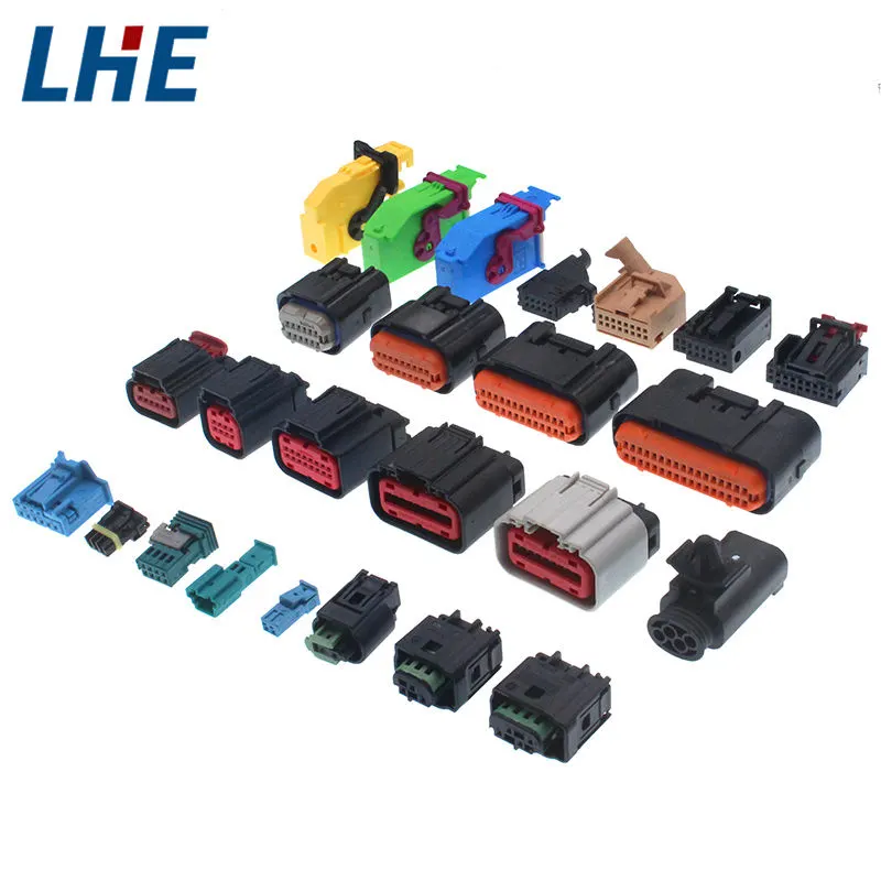
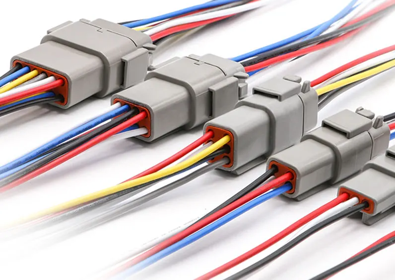
An electric connector is an electro mechanical device used to create electrical termination and create electric circuit. Electric connector consist of Housing, Terminal, wedge locks, seals, cavity, mounting cams, etc. These are responsible to make connection between harness and component.
Following Parameters are required to define for any connector:-
1- Geometric Parameter - Points and Co- ordinate system (Axis)
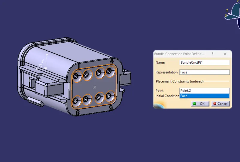
2- Connector Connection Points - This points is used for the connection of one connector with another connector
3- Harness Bundle Entry Point - This Point define where bundle segment point will end when routed to the electrical connector
4- Cavity Connection Point (Optional) - This point is used to define the connection of a connector with mounting clips. This only applies when the connector have the mounting feature for mounting clips.
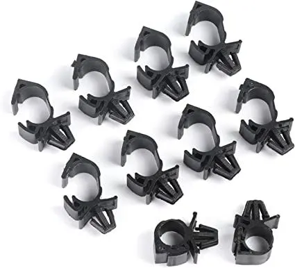
CLIPS & CLAMPS
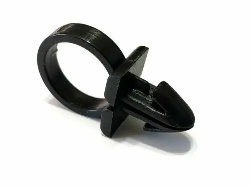
Clips are used for harness clamping in every area of vehicle. These are plastic molded parts with mounting/ snapping feature.
PROCESS
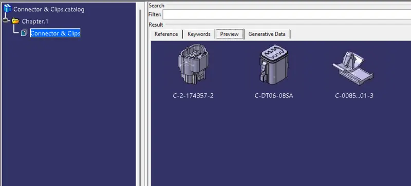
Connector 1- Deutsch DT06 – 08SA
Defining Connectors:-
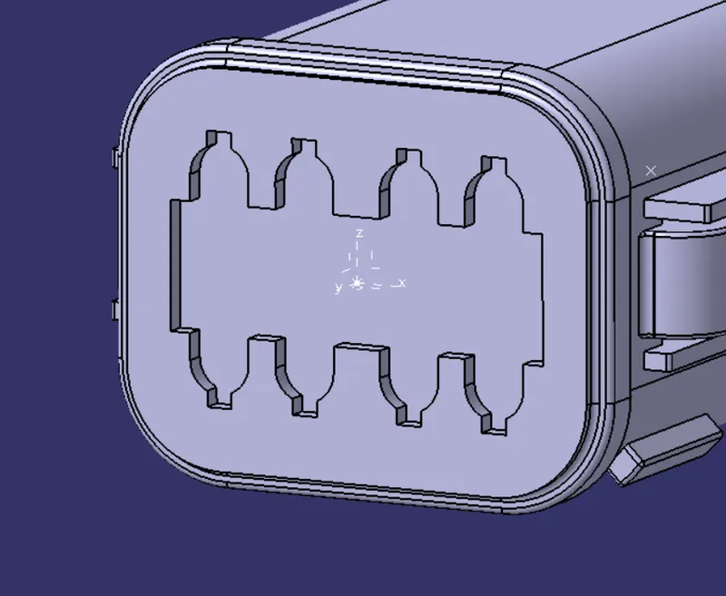
1- Create / download Connector 3D
2- Create required Geometrical parameter. Create 2 points on the middle of both ends of the part and Create a axis system on the mating face. Put Y axis to the other Mating part and X axis towards the Locking system
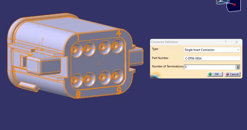
3- Define Part as a Connector
4- Define " Bundle Connection Point "
5- Define " Connector connection Point "
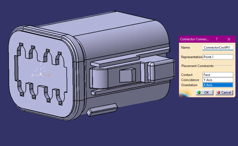
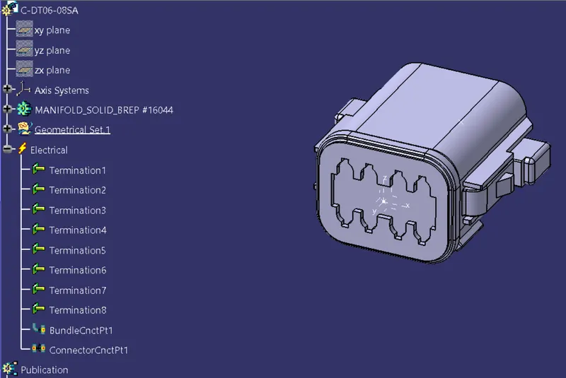
Connector 2 - Tyco 174357-2
1- Create / download Connector 3D
2- Create required Geometrical parameter. Create 2 points on the middle of both ends of the part and Create a axis system on the mating face. Put Y axis to the other Mating part and X axis towards the Locking system
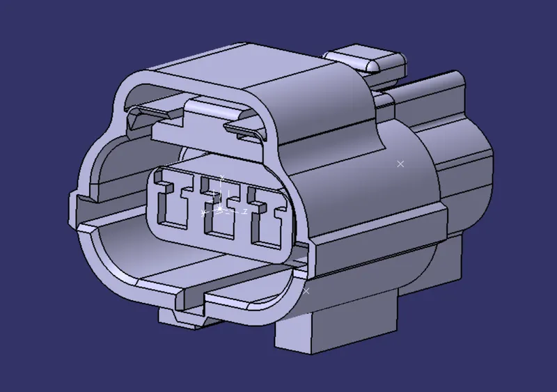
3- Define Part as a Connector
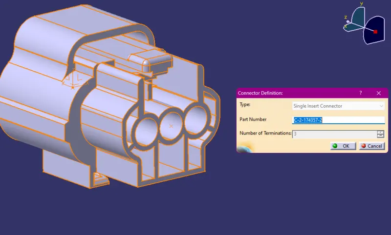
4- Define " Bundle Connection Point "
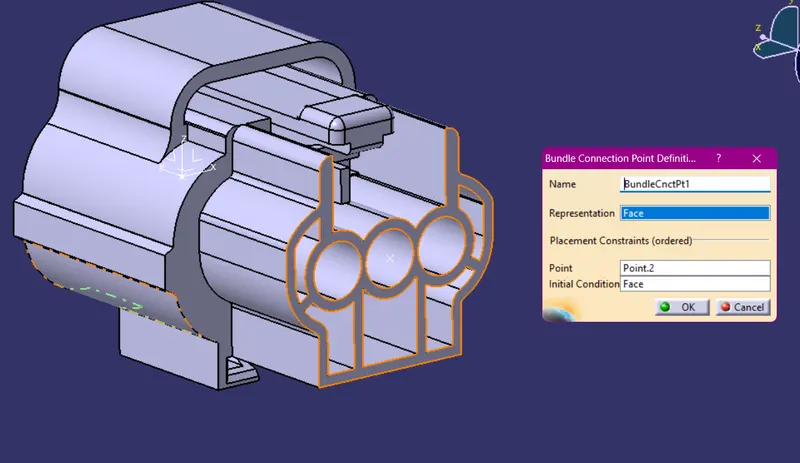
5- Define " Connector connection Point "
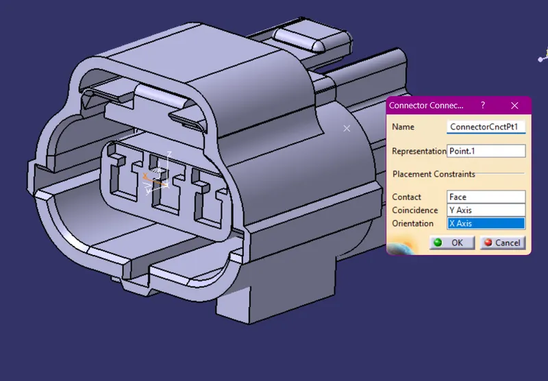
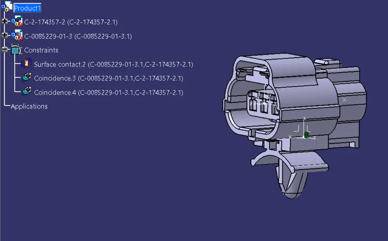
6- Create a Axis system on the Mounting Clips Lock Mechanism
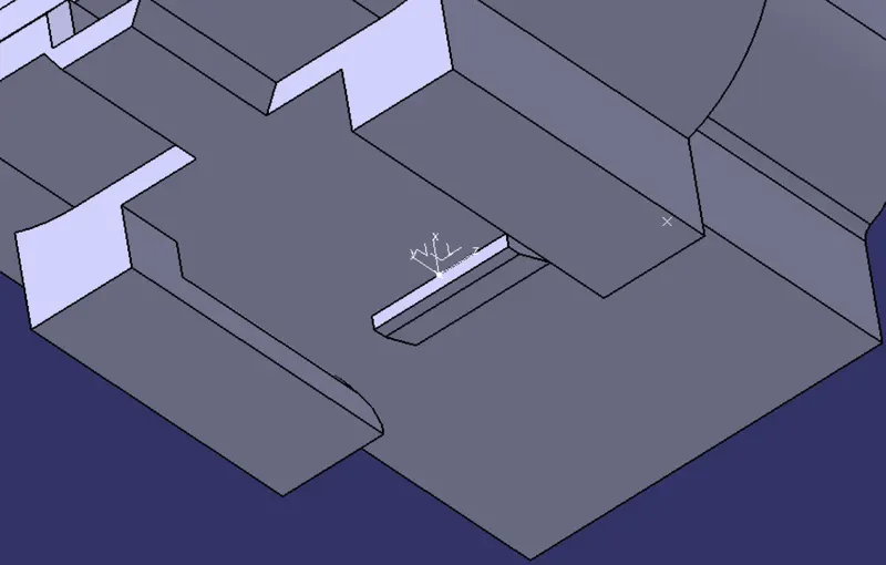
7- Define " Cavity connection Points "
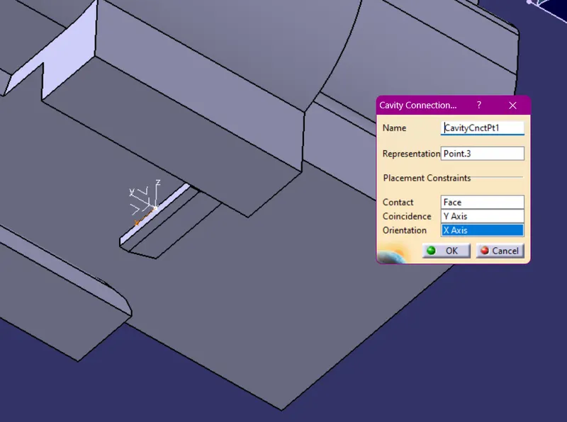
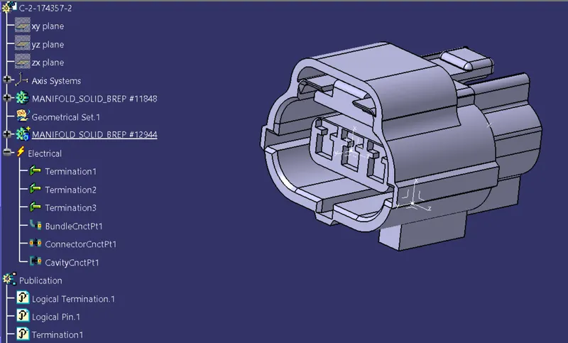
Defining Mounting Clips:-
1- Get the Clip 3D Part
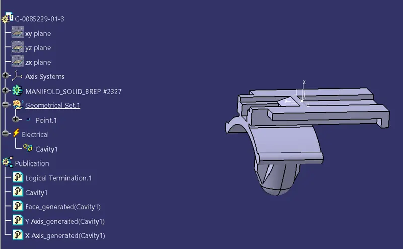
2- Define the geometry parameter. Put the Y axis
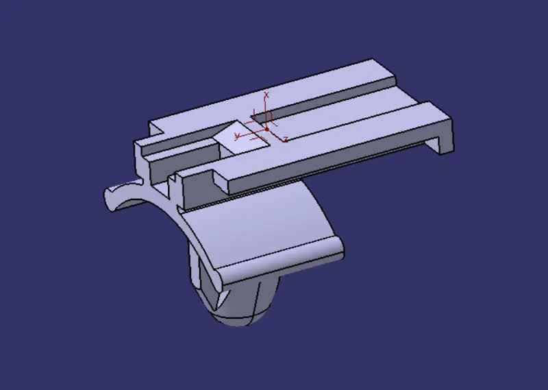
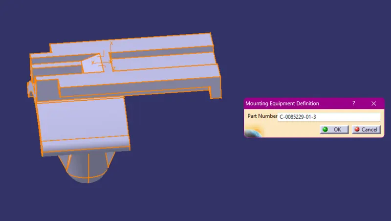
3- Define Part as mounting component
4- Define the Part as Cavity
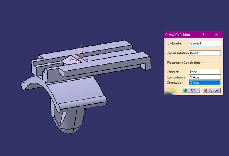
5- Join the Connector and Cavity
Catalog of Components