Wiring harness design in CATIA V5 - 3D modeling Week 2 Challenge
Q.1]
Objective :
Download following connectors & Connector clip cad data from given link & define it as Electrical Connector using Electrical Part design Workbench. Define all the necessary properties to Connectors & Clip.
- Deutsch DT06 – 08SA ( https://www.te.com/usa-en/product-DT06-08SA.html)
- Tyco 174357-2 (https://www.te.com/usa-en/product-2-174357-2.html?source=header-match)
- Tyco 85229-1 – (https://www.te.com/usa-en/product-85229-1.html?q=85229&source=header)
First we want to download these files and then open it in the CATIA environment.
Before building the model, we want to know the exact procedure for the Electrical Connector using Electrical Part design Workbench.
Wiring Harness :
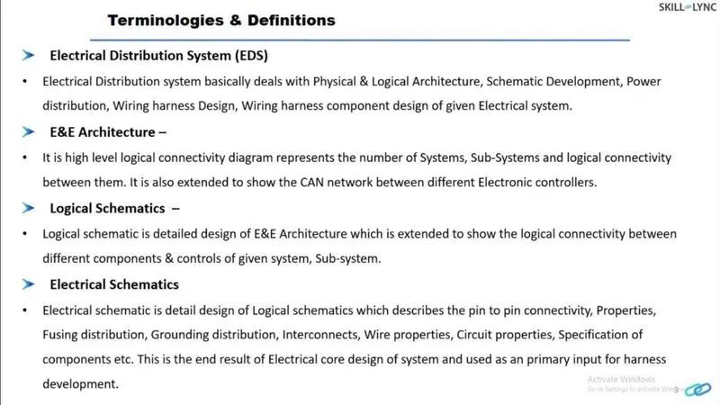
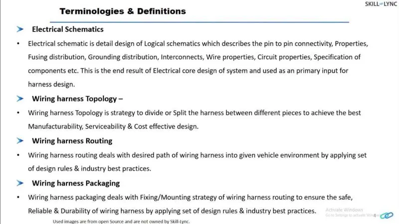
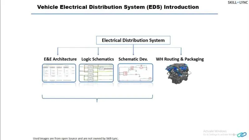
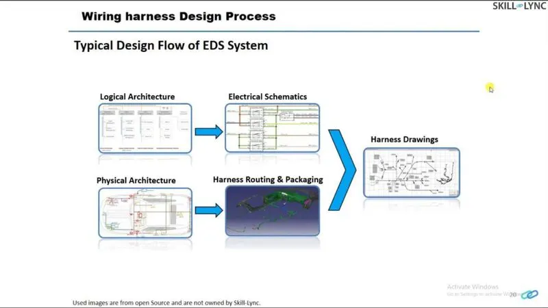
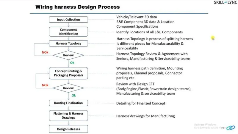
Defining the Electric parameter flow chart for the Connector Definition in CATIA V5
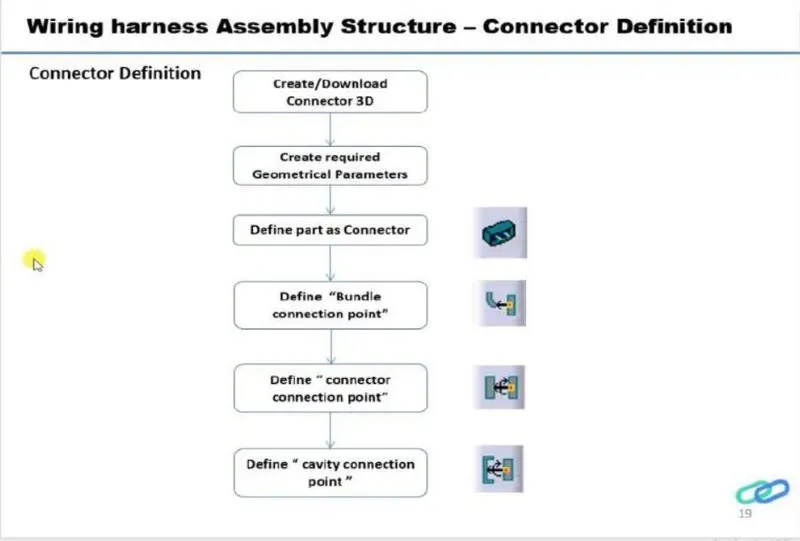
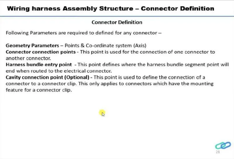
Connector Definitions in CATIA V5
1. Deutsch DT06-08SA
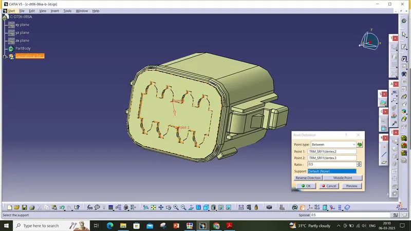
First we want to create the required Geometrical Parameters for the Connector Definition.
Create midpoint on the contact face which will connect the other connector to it.
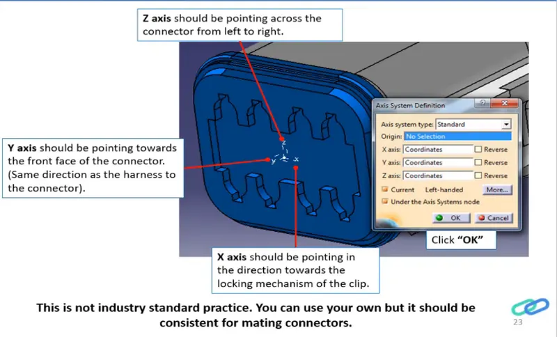
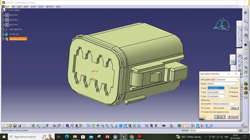
Craete Axis System with respect to the point which we have created and defining the axis direction as shown below,
Bundle Connection Point :
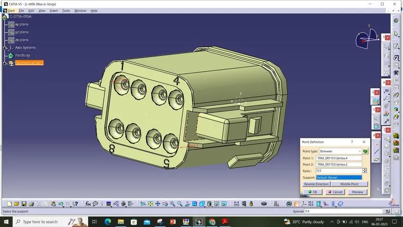
Now the geometrical parameters are defined, So then we'll move to define the 'Electrical Part Design'
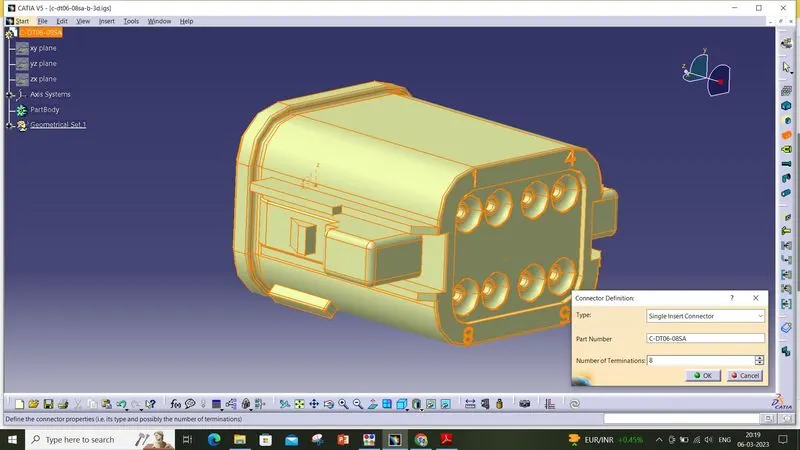
Define the part as connector in catia, give no. of termination as 8 because we have 8 entry points for wire.
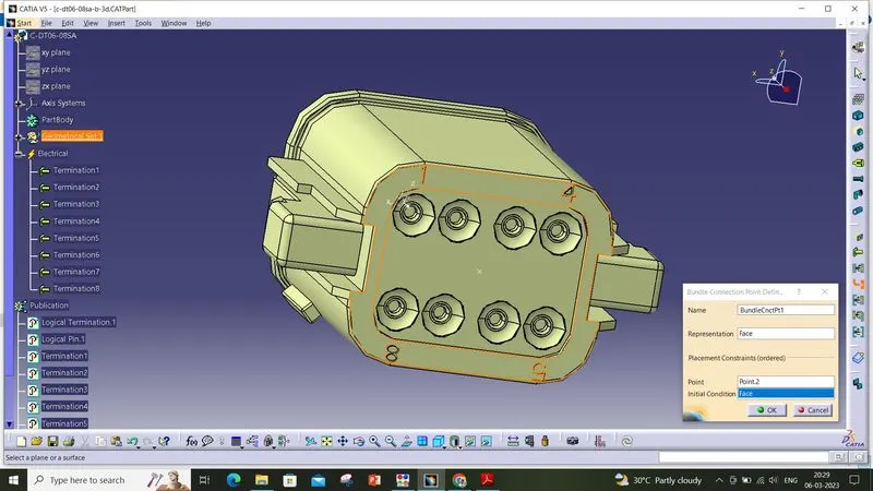
Define Bundle connection point
Define connector connection point
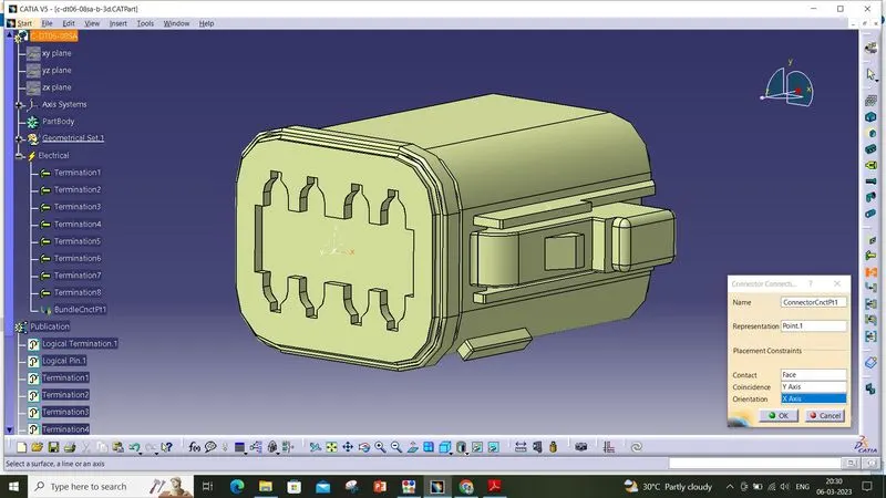
So, the definition for electrical connector creation is completed for this connector. It is ready for the assembly.
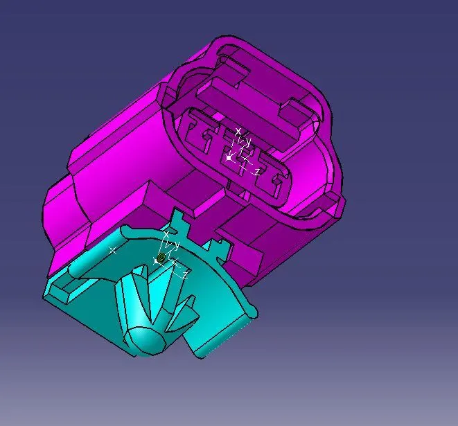
2.174357-2 :
Repeat the above Electrical Connector definition procedure for this connector.
- Create midpoint for the contact face
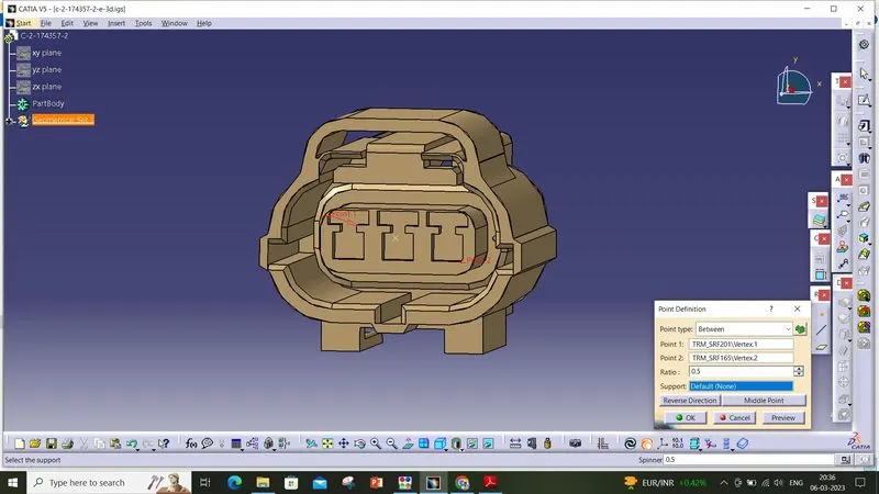
- create Connector connection point
- create Connector connection axis system
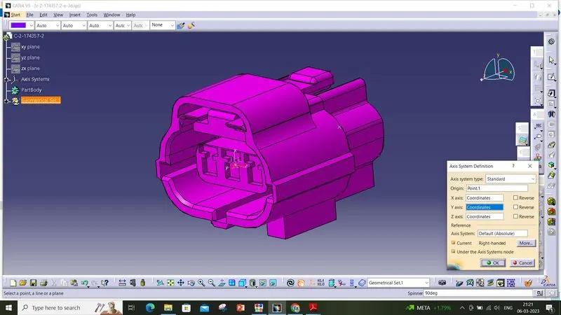
- create cavity connection point
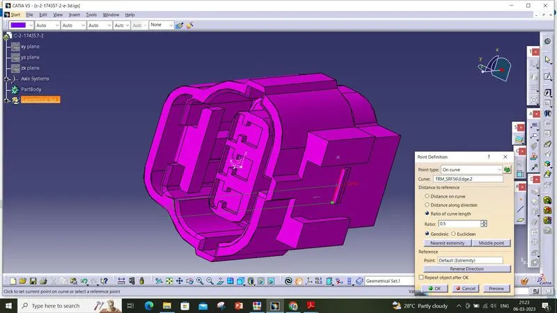
- create cavity connection axis system
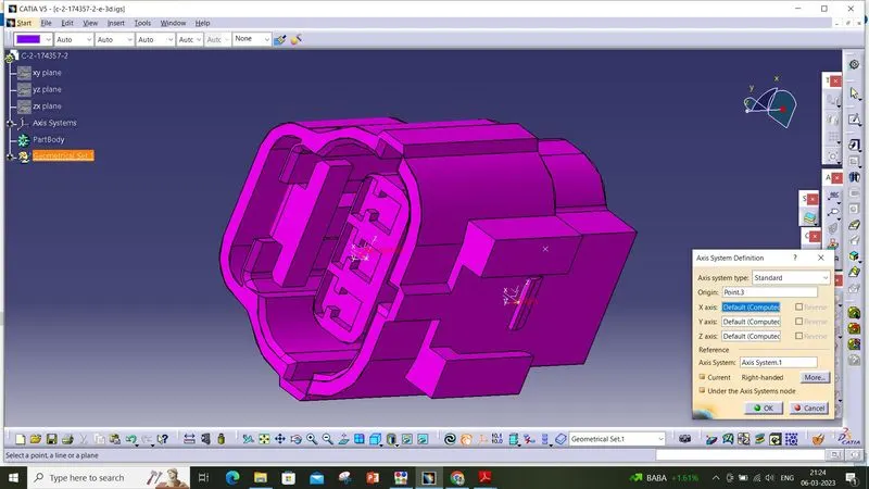
- Switch to Electric part design and define part as connector
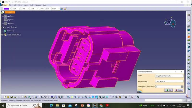
- Define Connector connection point and cavity connection point
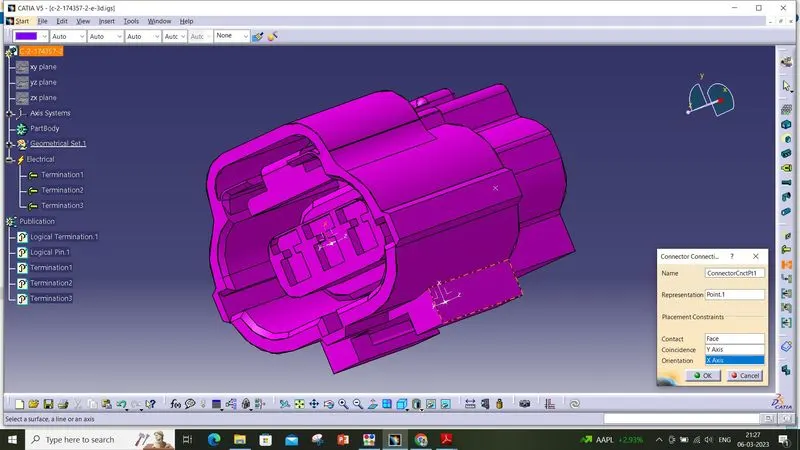
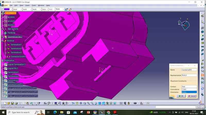
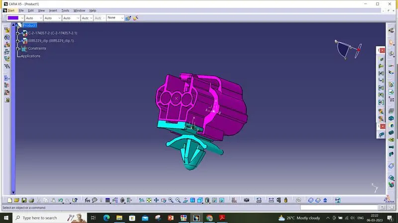
3] 85229-1 :
This is the connector clip which used to mount the clip in the required surface.
- Create midpoint
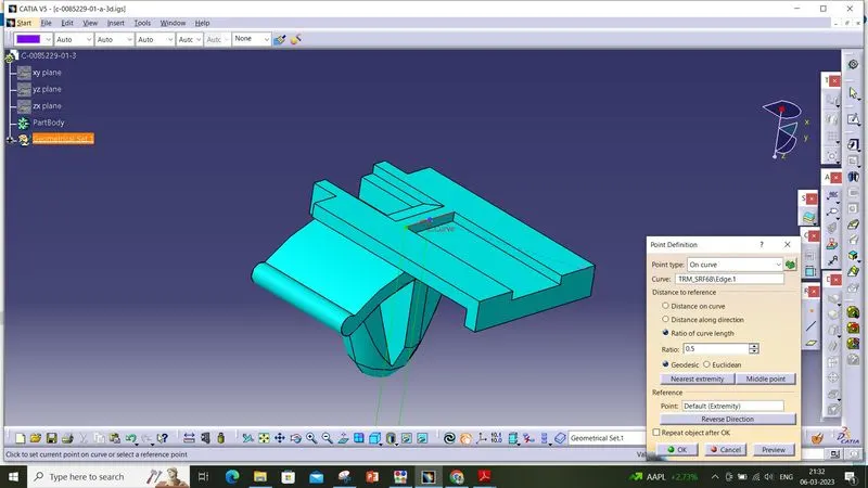
- create cavity connection axis system and orientation should be same as in connector
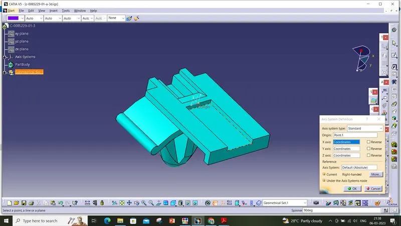
- Switch to Electric part design and define part as Mounting Equipment
- Define cavity connection point
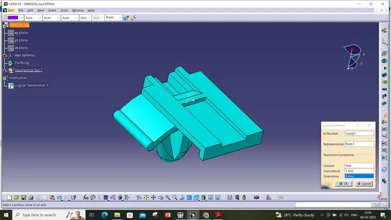
Electric Assembly Design
Then create one new part which was the Electrical Assembl Design and then import these 3 Connector and cavity / mounting clip.
By using the connect electrical device tool, we'll connect them in appropriate manner.
For the first two connector it'll not connected because the terminations in the connectors has varies. Because the first connector has 8 terminations and the second connector has 3 terminations.
So the second clip and the mounting clip was connected each other in a good manner by using the connect electrical devices tool in the assembly which was shown below.
Finally the connector and the mounting clip is conneccted.