Project - Speed Control of a Direct Current (DC) motor
Project - Speed Control of a Direct Current (DC) motor
In this project, a Simulink model for the DC motor will be first developed per the schematic shown in Figure 1.
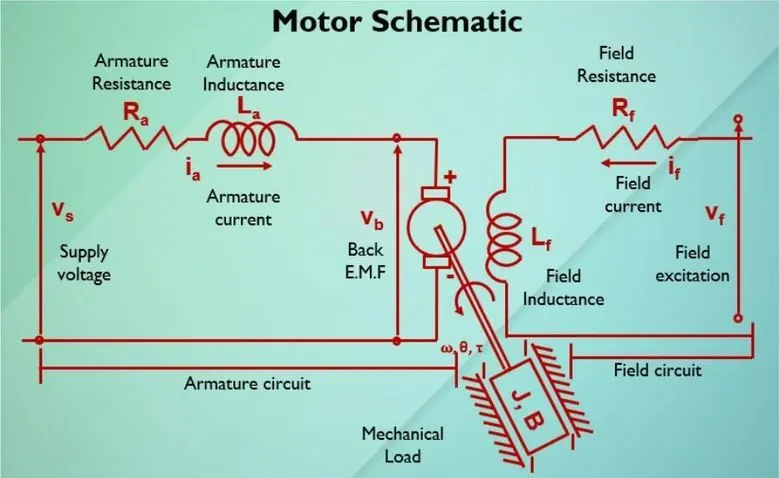
Speed Control Methods of DC Motors: The speed can be controlled by varying
(i) Flux/pole, Φ (Flux Control)
(ii) Resistance Ra of armature circuit (Rheostatic Control) and
(iii) Applied voltage V (Voltage Control)
In this project, I decided to use the armature circuit control method.
In the week 8 lecture, we studied the DC motor design and control methods.
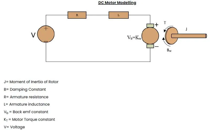
For DC Motor modeling, we have the formulas,
Motor Torque T= Kt*I
Back EMF Vb= Kb*w = Kb* dtheta/dt
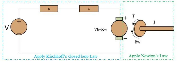
By using Kirchoff's closed-loop law and Newton's law, then converting them into a transfer function, then we get this equation.
The open loop transfer function for the motor with speed(w) and supply voltage (Vs) can be derived as,
w(s)/v(s) = Kt / [ (Ls+R) (Js+B) + Kt*Kb]
By using this formula, we found how the DC motor is modeled mathematically with the ‘s’ domain and state space model equations.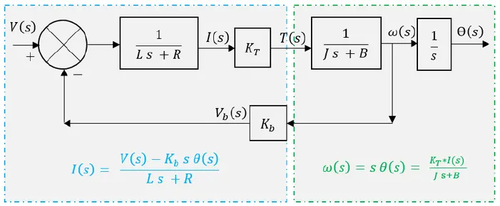
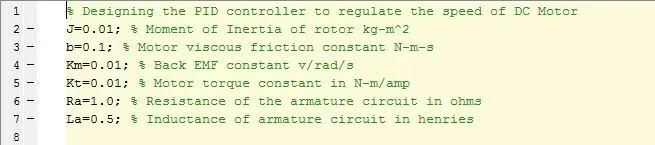
I'm giving the constant values of the motor and state space equation which were determined by the transfer function.
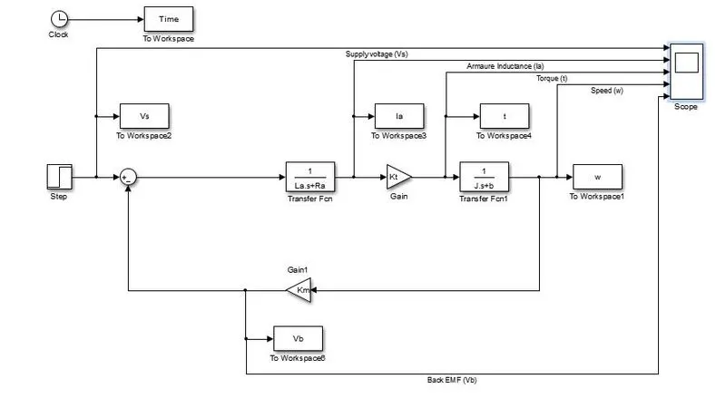
I created the Simulink model for the above formula,
w(s)/v(s) = Kt / [ (Ls+R) (Js+B) + Kt*Kb]
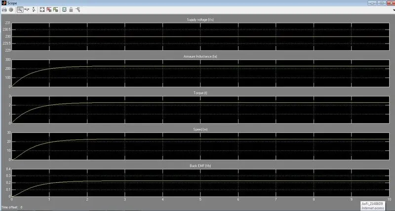
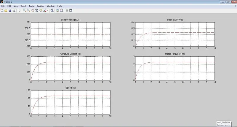
When running this model, I'm getting this output.
Use the Proportional, Integral, and Derivative (PID) control design knowledge gained in the training to design, develop and test a controller to maintain a desired speed for the motor.
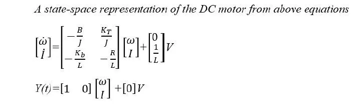
We know that the state space equations for DC Motor,
x_dot = Ax + Bu
Y = Cx + Du

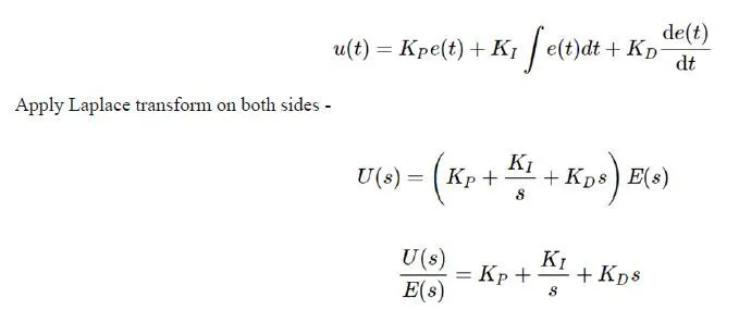
We know that Mathematically PID controller can be defined by the following equation where e(t) is the error signal with respect to time Kp, Kd, and Ki are PID constants.
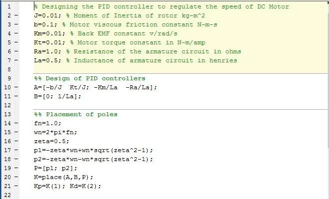
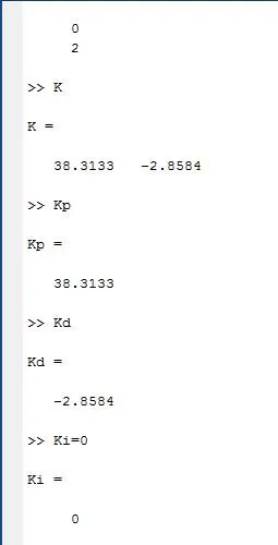
From the above script, we can determine the controller gain parameters Kp and Kd, from the location of poles p1 and p2 using the ‘place’ command in MATLAB. The Ki is tuned manually and Kp and Kd values are taken from the place command.
We are having these 2 types of PID controller methods.
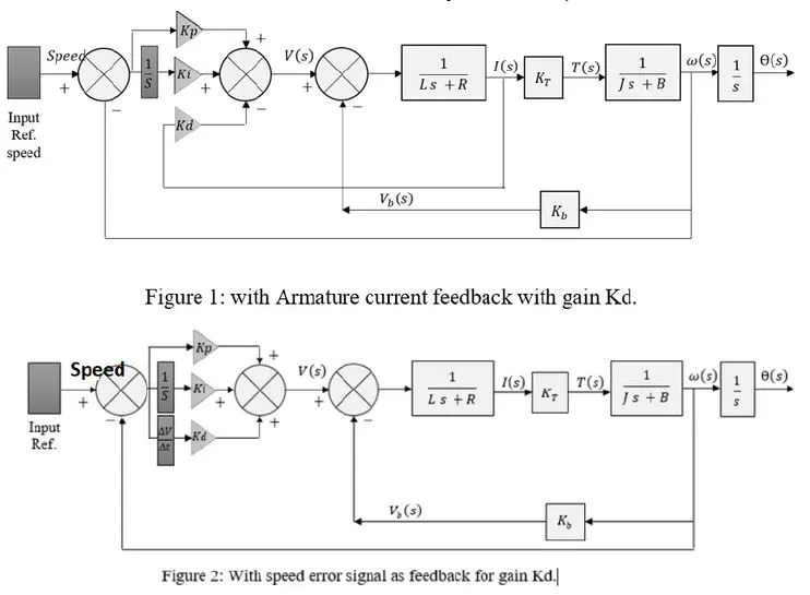
I've taken the 2nd type model that was "with speed error signal as feedback for gain Kd."
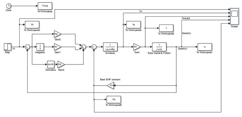
Initially, I take the Ki value as 0.
When I run this model I'm getting this output,
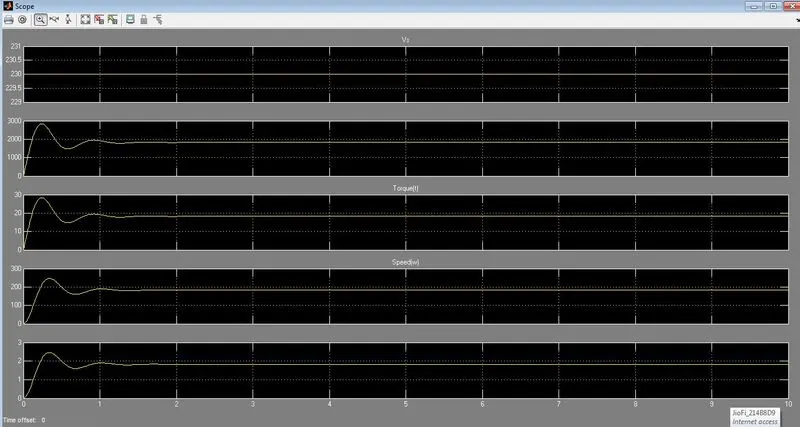
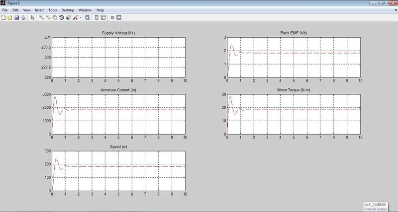
But we have to meet this PID design objective,
Select the P, I, and D gains such that the control design objectives for settling time, overshoot, and steady-state error are met.
We know that the design objective of PID design,
Setting time < 2 sec
Overshoot < 5 %
Steady-state error < 1%
And have these recommendations,
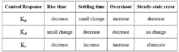
We know that
Kp - Proportional gain is used to increase the system response speed and reduce steady-state error.
Ki - Integral gain is used to eliminate the steady state error at all [Ki=Kp/Ti(time constant)] but it produces an unwanted increase in the response overshoot.
Kd - Derivative gain used to reduce the system response overshoot [Kd=Kp*Td(derivative constant)].
We want to use the tuning methods of PID controllers in this for getting better results.
So we have to satisfy these requirements, so I decided to have the figure for Time VS Speed (w)
For Ki=0, it gives this output,
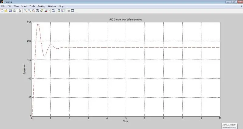
We want to maintain the desired speed for the motor by tuning the control gains of the PID controller.
Here I changed some values to tune the speed for the DC motor, that was shown below
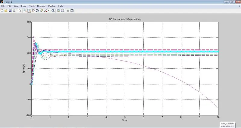
So now we know that if we use a PID controller with Kp=70,ki=250, and Kd=2; all our design requirements will be satisfied and the response looks like this,
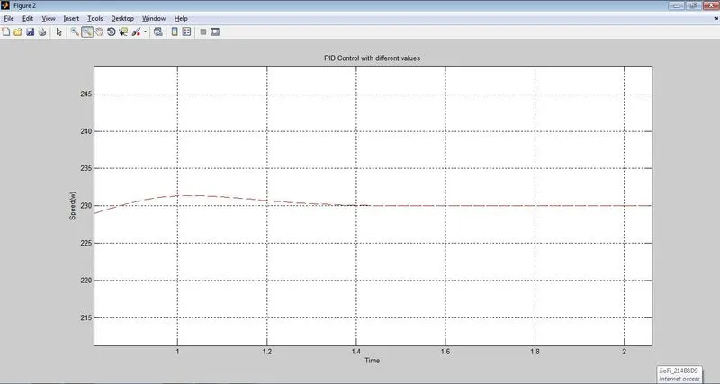
Maintaining desired speed in the motor is obtained by using these PID controller values.
Stability of the system :
The location of the poles decides the stability of the system. This is shown in the below figure for critically stable, unstable, and stable systems.
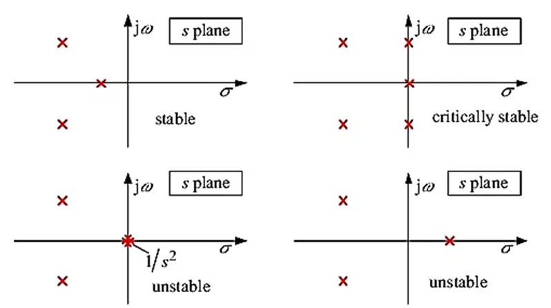
You can see two crosses in red indicating complex poles lying on the lefthand of the plane which indicates it is a stable system.
I'm using this script to find out whether our system is stable or not.

When we run this above script, we'll get this output
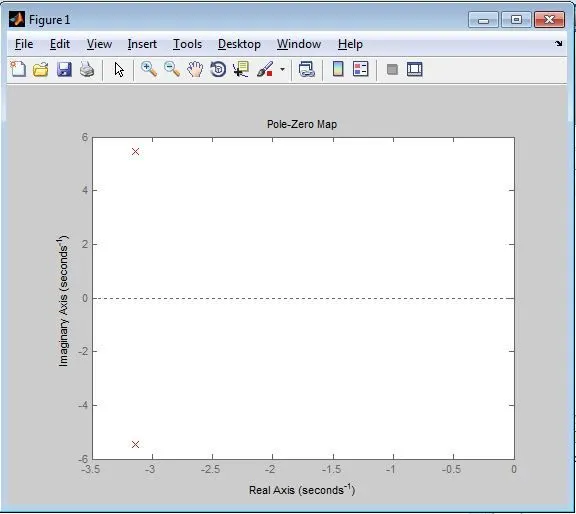
From the above reference, we found that our system is the stable one.
And also we can use directly PID Controller block to control the speed of the DC Motor instead of using the mathematical way.
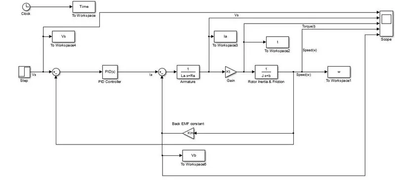
When I run this, I'm getting the same way of output.
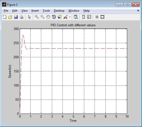
So now we know that if we use a PID controller with Kp=70,ki=250, and Kd=2; all our design requirements will be satisfied.