Wiring harness design in CATIA V5 - 3D modeling Week 2 Challenge
First we download the required document from the given links in challenge screen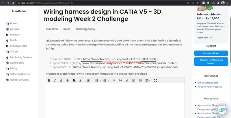
Click the link its direct to the te.com website for more details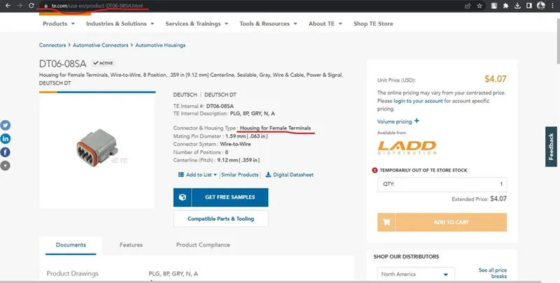
Then check the part no and name and check for other details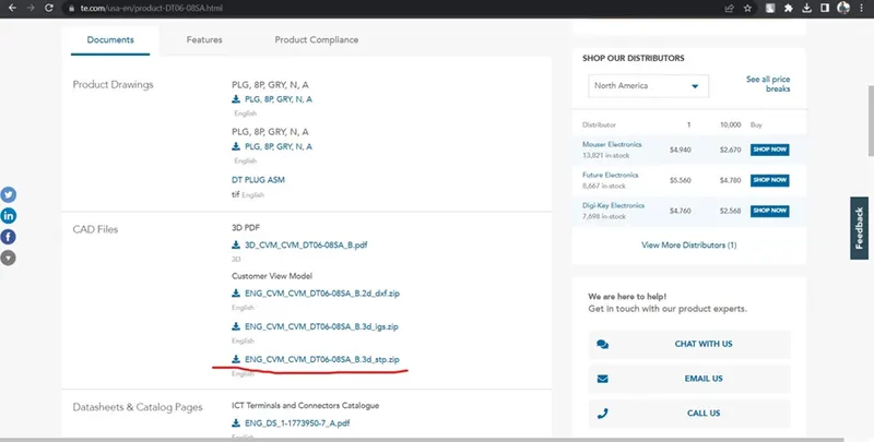
Download the CAD in .stp format
.stp is the universal format for CAD file support in all type of modeling software
Extract the downloaded file by and open with CATIA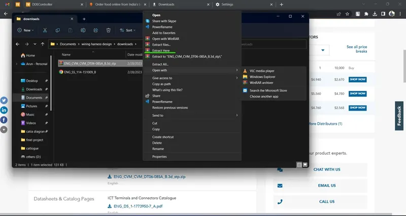
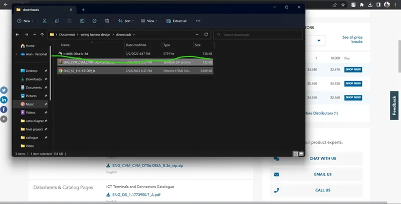
CATIA will convert it and show the product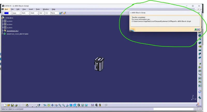
Then save the file in CAT part format to make easy future usage in assemblies.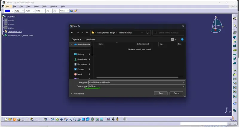
Define the part in mechanical to create connector connecting point axis and bundle connecting point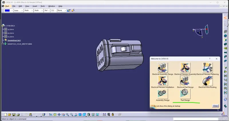
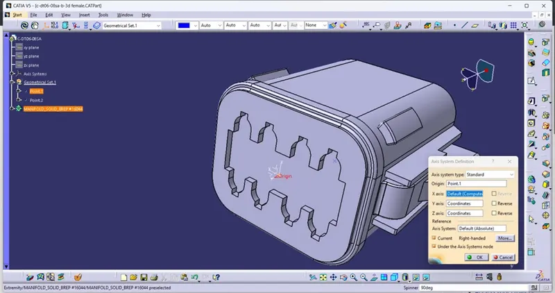
After create the connecting point and axis system switch to electrical part design to define the part as a connecter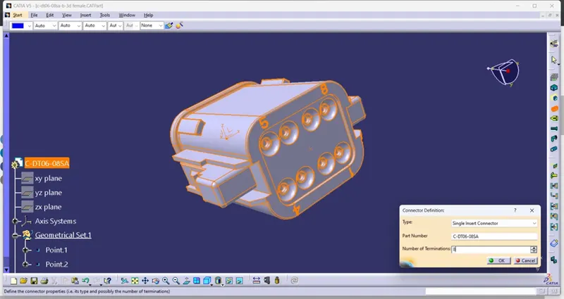
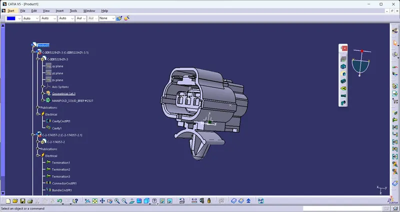
After define the connector as an electrical part see the tree the part is defined as electrical and no of termination we give are shown.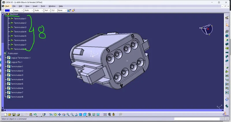
Next define connector connection point.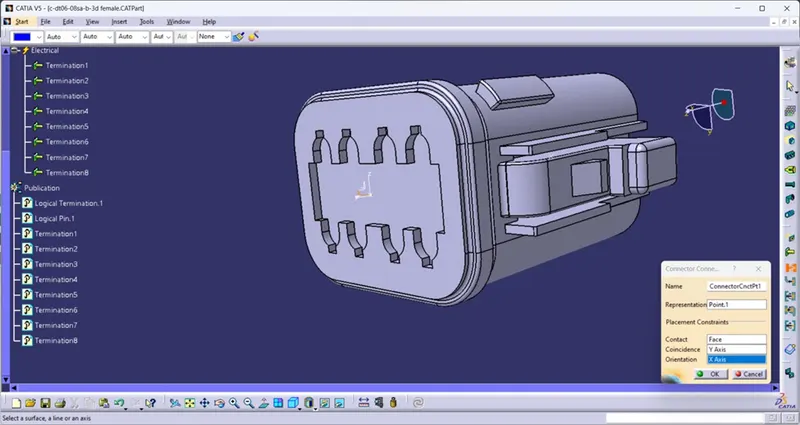
Select the point as a representation, contact is face of the mating surface coincidence y axis, orientation x axis.
Then create the bundle connection point using the tool ‘define bundle connection point.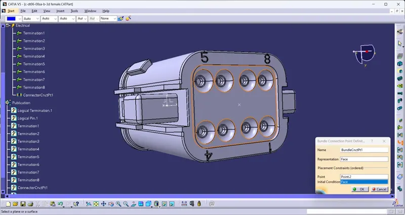
Next go for the next connector part download it from the given link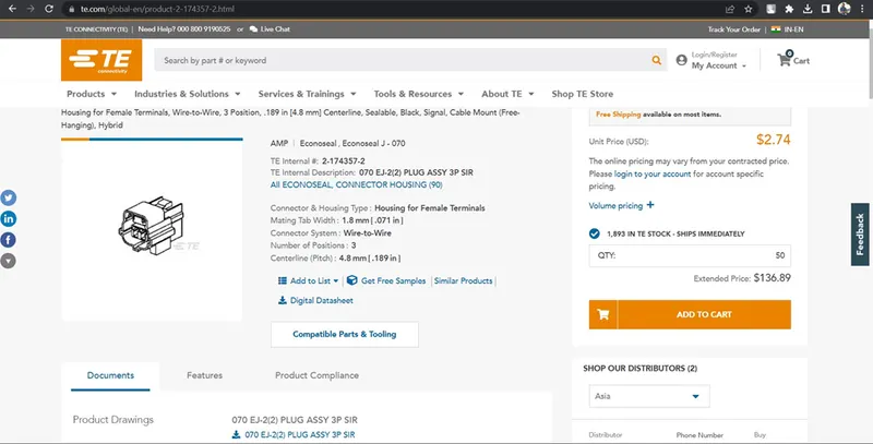
Make the necessary point and axis system for create connector connection point and bundle connection point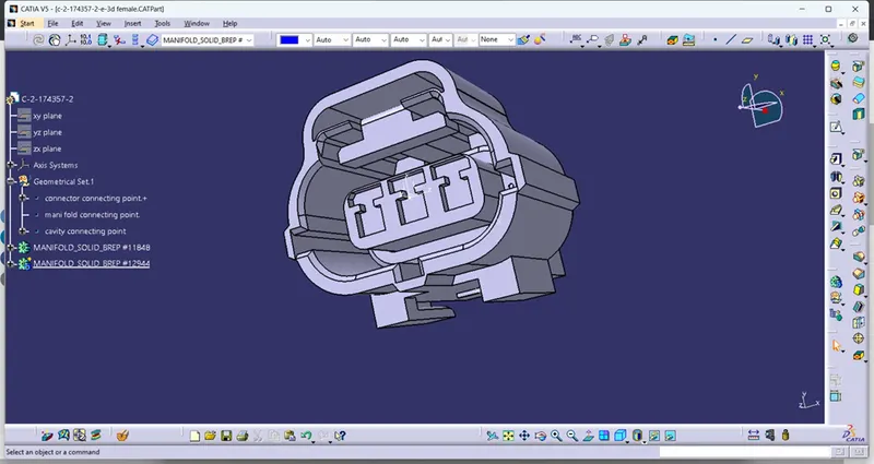
Define as connector with three terminals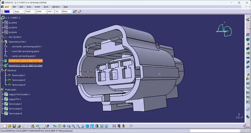
Create the connector connection point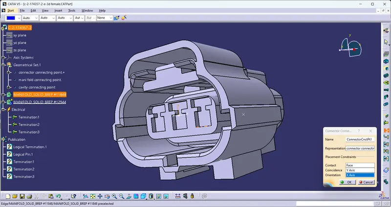
Creation of bundle connection point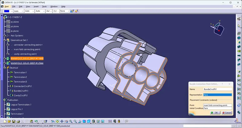
Create the cavity connection point.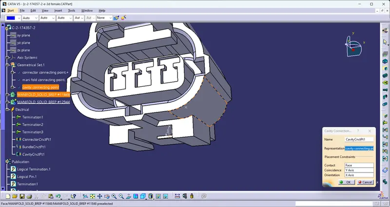
Next go for the clip
Design as a clip and cavity also for connecting to the connector.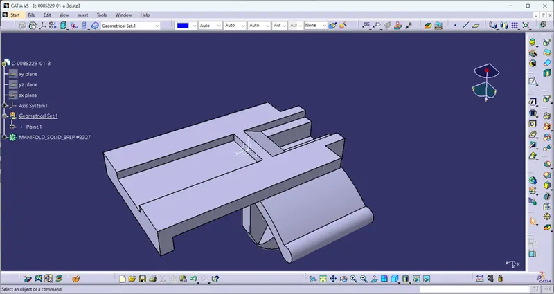
Finally assemble the clip and the female connector in electrical assembly work bench