Project - Speed Control of a Direct Current (DC) motor
Project tittle-speed control of DC motor
Aim:
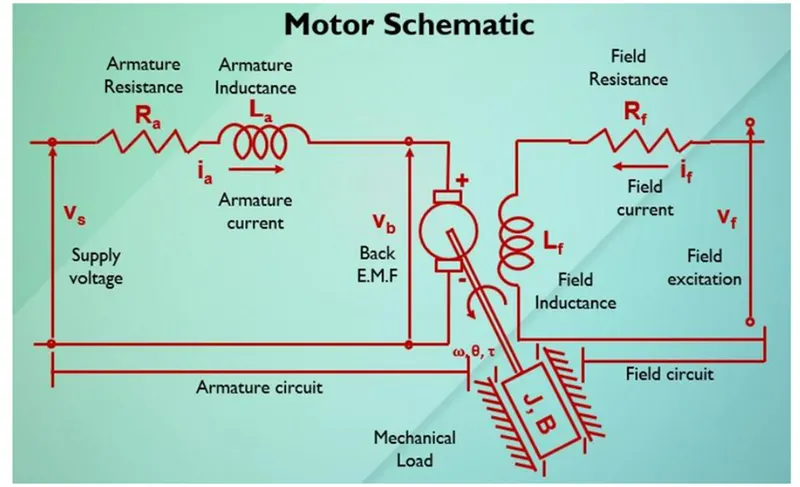
Create a Simulink model for the dc motor developed per the schematic shown below and use the proportional, integral and derivative (PID) control design.
Summary:
First we create a Simulink model for the dc motor for the below schematic
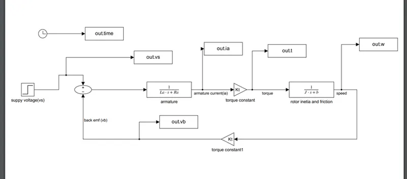
And the Simulink model is shown below:
The plots made for the above model are
Time vs supply voltage
Time vs armature current
Time vs torque
Time vs speed
Time vs back emf
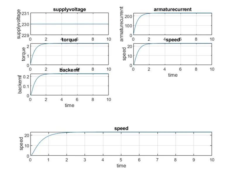
From above plot we know about the speed control variables of dc motor.
Parameters used in PID controller:
% This file contains parameters for DC m
J=0.01; % Inertia
B=0.1; % friction
 Km=0.01; %back emf
Kt=0.01; % torque
Ra=1; %resistance
La=0.5; %inductance
 % Design of PID controller
 A=[-B/J Kt/J; -Km/La -Ra/La];
 B=[0 ; 1/La];

% Placement of Poles

fn=1;

wn=2*pi*fn;

zeta=0.5;

p1=-zeta*wn+wn*sqrt(zeta^2-1);
 p2=-zeta*wn-wn*sqrt(zeta^2-1);
P=[p1; p2]
k=place(A,B,P)
kp=38.3133;
kd=k(2);
ki=20;
Simulink for PID control of the dc motor:
The above fig shows the PID control design of the dc motor:
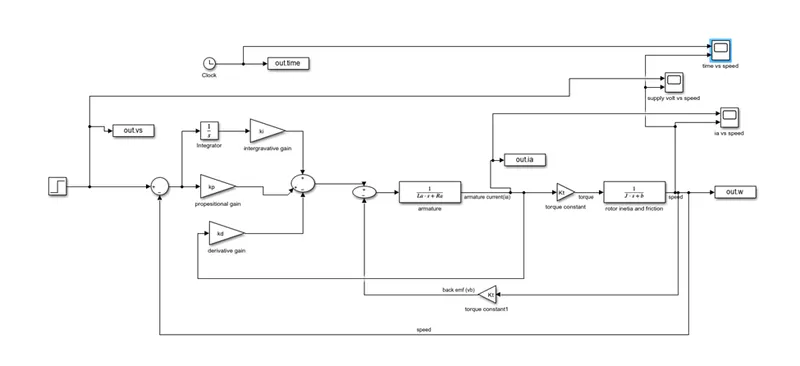
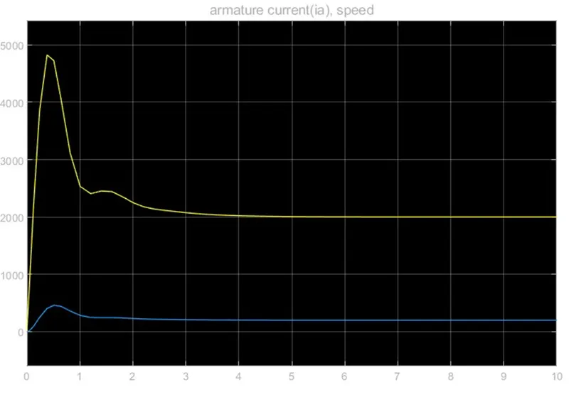
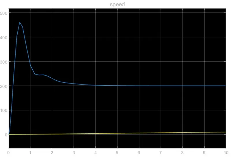
And plots are below
Armature current vs speed
Supply voltage vs speed:
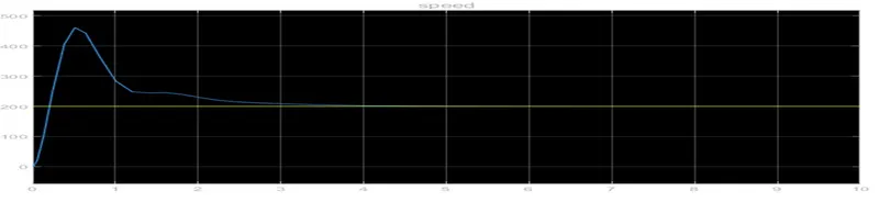
time vs speed:
Conclude:
As we conclude with the design and control of dc motor with PID controller.
Special thanks to Sanjeev Kumar Rajoria skill lync employee to asset me to complete the project.