Wiring harness design in CATIA V5 - 3D modeling Week 2 Challenge
Aim
To define the given connectors electrically amd define the necessary properties to the connector and clip.
Wiring harness
Wiring harness is the assembly of wires ,connectors,terminals,protection coverings, insulations,clips,clamps,fause and relay box,retention devices,u guiding channels,electronic components.a system of insulated conducting wires bound together with insulating materials ,used in the electrical system of machine.
Connectors
An electrical connector is a electro mechanical device used to join electrical termination ands create electric circuits. Electric connectors consist of housing,terminals,wedge,hooks,seals,cavity,mounting clip etc..
Connectors are plastic molded housing with locking and retention feature.
Connectors parts
Connector
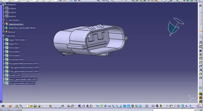
Mating part
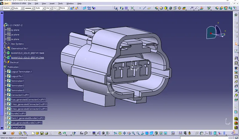
Male part
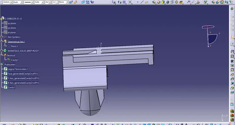
Mounting clips
Methodology used for creating the connector assembly
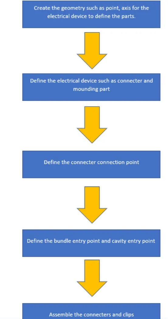
Types of workbenches used
- Mechanical part design
- Electrical part design
- Electrical assemble design
Mechanical part workbench
In this workbench the required geometrical paramters are created in the workbench.
1) points
2) Coordinate system
Electrical part design
Here the mechanical parts are defined into the electrical parts .
Define connector
This option is used to define the connector as electric part . Here the the number of terminals is indicated at initially.
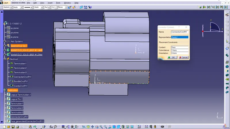
Define connector connection point
This point is used to joining the male and female parts of the connector. Its placed at the ating suface .
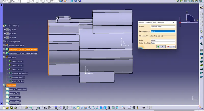
Define bundle entry point
This option is used to define the bundle entry point at one end of the connectrs where the wire bundles are enetered .
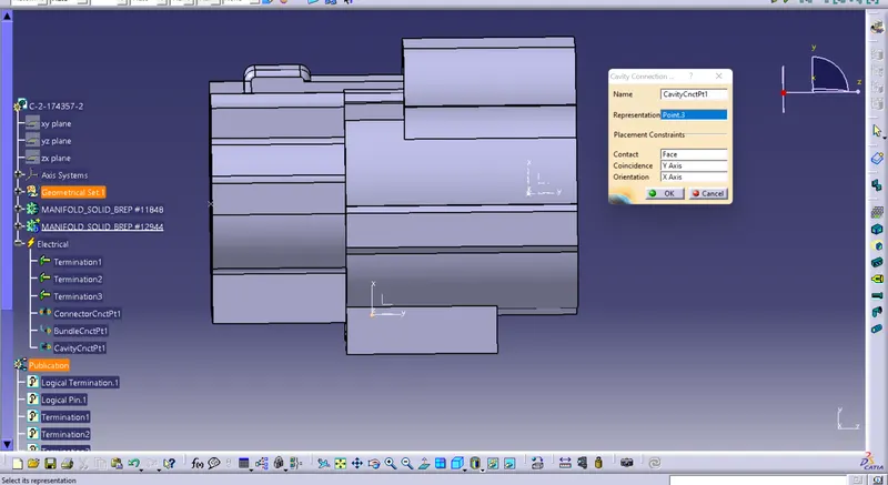
Define cavity connection point
This point is used to define the mounting point for the clips.
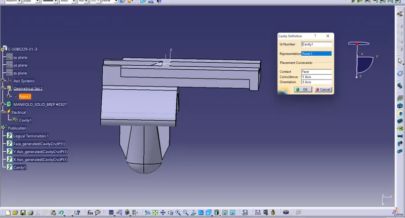
Define cavity
Initially the given clip is defined as the mounting equipment. After that the cavity point is defined .
Electrical assembly workbench
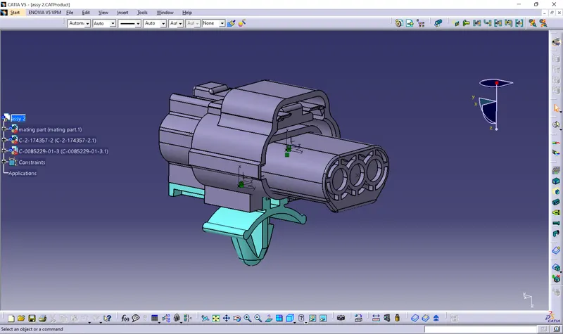
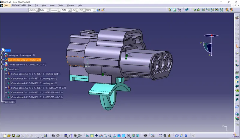
In this workbench all the defined electrical parts are assembled . The assembly is created depends on the defined connection points and axis systems.
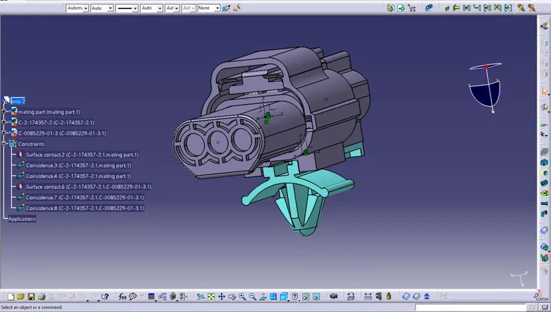
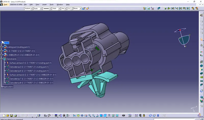
Final product assembly
Conclusion
The given connector and mounting clips are assembled by using electrical assembly and the required geometrical parameters are created in electrical and mechanical part design