Wiring harness design in CATIA V5 - 3D modeling Week 2 Challenge
INTRODUCTION TO WIRING HARNESS
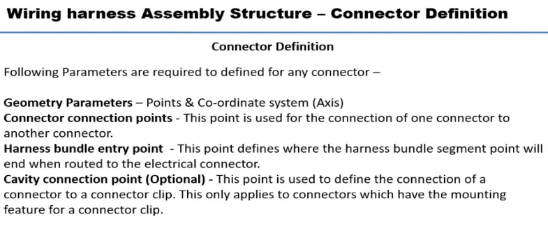
CONNECTOR DEFINITION IN CATIA V5
1.Tyco 174359-2:
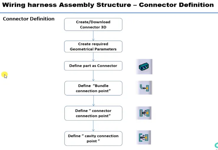
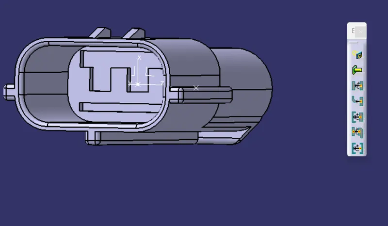
Connector Connection Point
- This point is used for the connection of one connector to another connector.
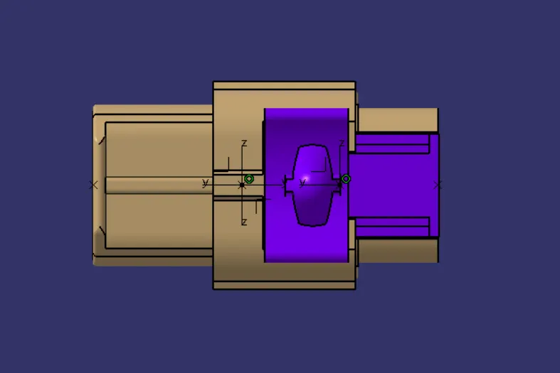
- Create a midpoint on the mating face.
- And create the axis on the origin point.
- Define the connector logical termination.
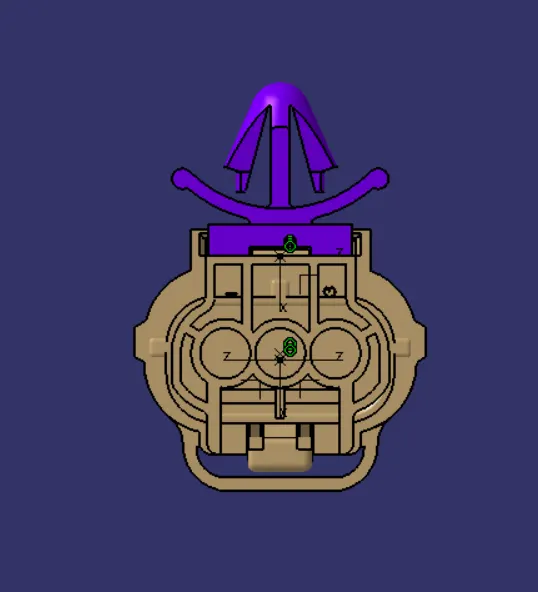
- Define the connector connection point and select the x,y,z representaion of directions.
- X-Axis consider the locking position of the connector.
- Y-axis consider as the coinsident of the connector.
- Z-axis consider as the left ,right movement of the connector.
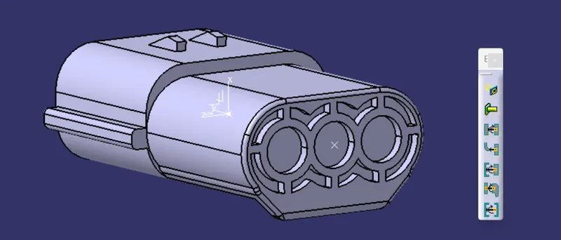
Bundle Connection Point
- This point is created for the wire entry position of the connector.
- Create midpoint of the entry face.
- Define the Bundle connection to select the normal face of the connector.
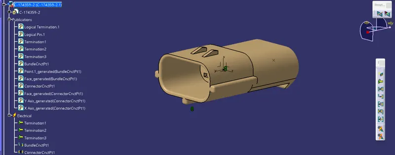
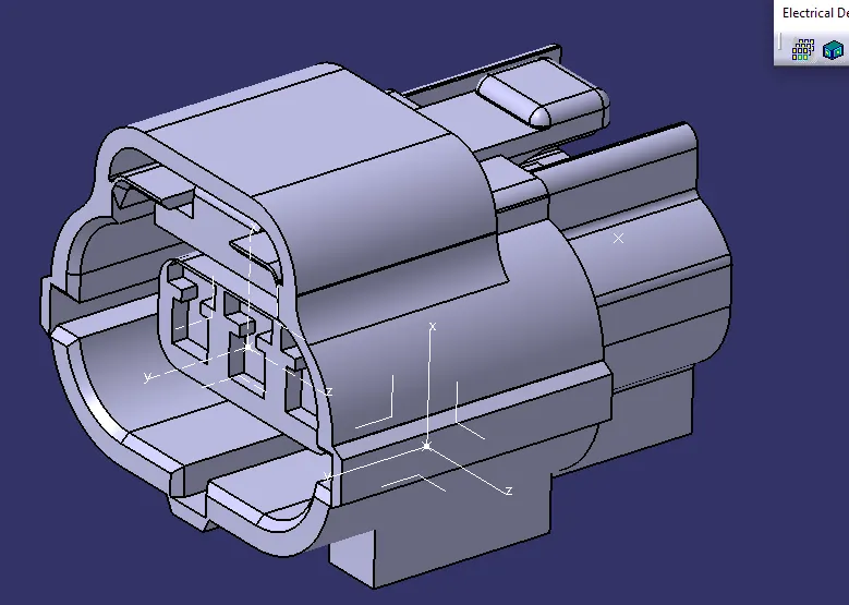
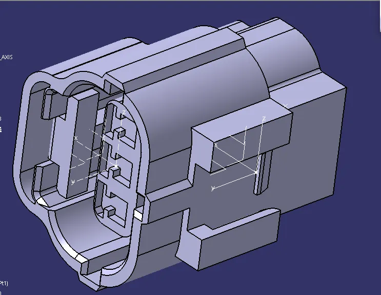
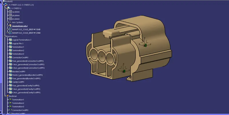
2.Tyco 174357-2 :
- Create midpoint.
- Create Connector connection point.
- Create Connector connection axis system.
- Create cavity connection point.
- Create cavity connection axis system.
- Switch to Electric part design and define part as connector.
- Define Connector connection point and cavity connection point.
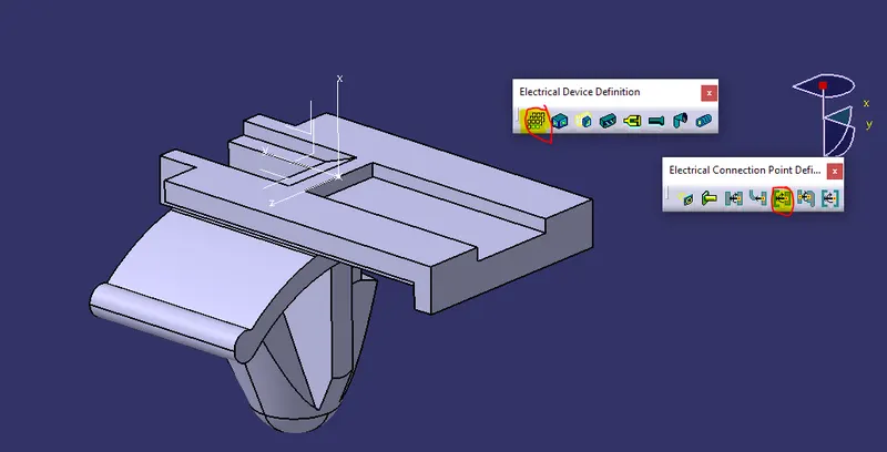
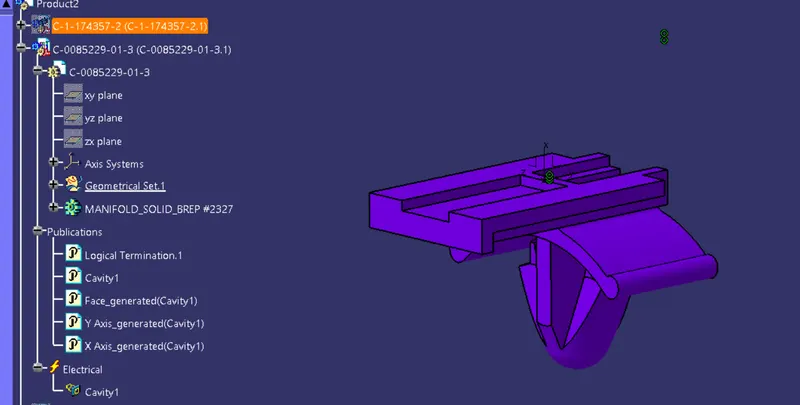
3. Tyco 85229-1 :
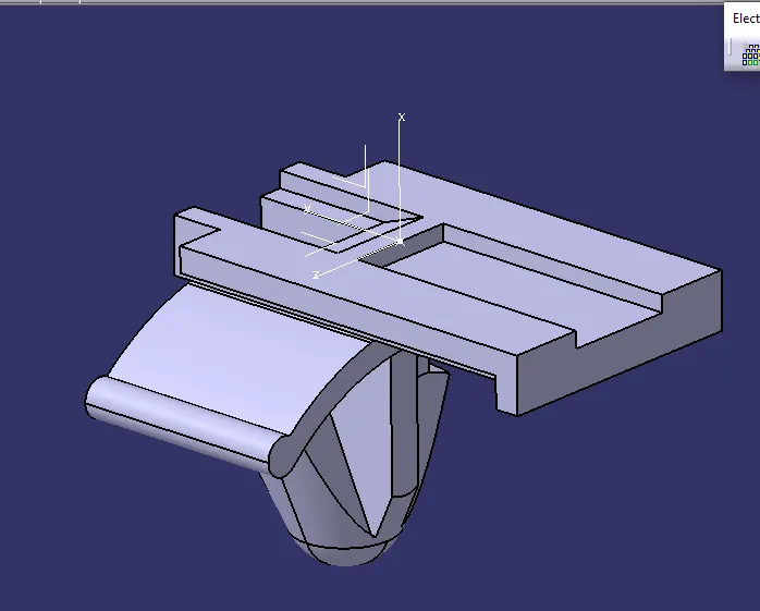
- Create midpoint.
- Create cavity connection point.
- Create cavity connection axis system and orientation should be same as in connector.
- Switch to Electric part design and define part as Mounting Equipment.
- Define cavity connection point.
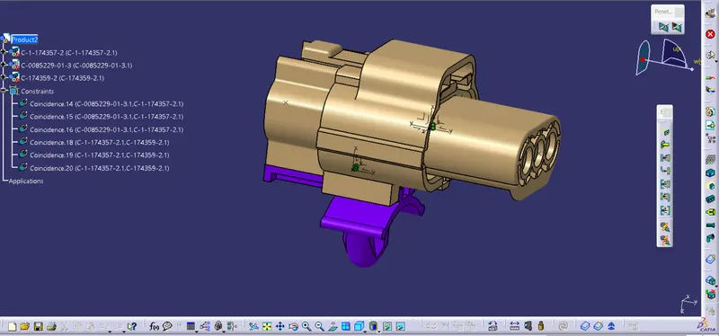
ELECTRICAL ASSEMBLY DESIGN:
- To Import the connector,cavity,clip product.
- To connect the assemble of mounting clip and connector.
- And then connect to assemble the male housing connector on the main connector.